Hak5 WiFi Pineapple Enterprise Comprehensive Technical Manual
The WiFi Pineapple Enterprise is an essential tool in the Hak5 pentesting ecosystem, engineered for stealth, efficiency, and full operational reliability.
Table of Contents
- ** 1. Product Overview & Hardware Architecture**
- ** 2. Initial Setup, Operating System Setup & Connectivity**
- ** 3. Web UI Overview, Recon, PineAP & Cloud C²**
- ** 4. WiFi Basics, Radios, Antennas & 802.11 Frame Mechanics**
- 4.1 Introduction to WiFi
- 4.2 Radios and Chipsets
- 4.3 Stations and APs
- 4.4 Transmit Power
- 4.5 Antennas
- 4.6 Channels and Regions
- 4.7 Protocols
- 4.8 Modes of Operation
- 4.9 Logical Configurations
- 4.10 MAC Addresses
- 4.11 Broadcast and Multicast MAC Addresses
- 4.12 SSIDs
- 4.13 802.11 Frame Types
- 4.14 802.11 Frame Structure
- 4.15 Management Frames
- 4.16 Frame Injection
- 4.17 Association and State
- ** 5. FAQs, Troubleshooting, Upgrades & Maintenance**
- 5.1 Establishing an Internet Connection
- 5.2 Configuring a Client Mode Connection
- 5.3 Configuring ICS on Linux
- 5.4 Configuring ICS on Windows
- 5.5 Configuring a USB Ethernet Adapter
- 5.6 Password Reset
- 5.7 Factory Reset and Recovery
- 5.8 WiFi Pineapple Updates
- 5.9 WiFi Pineapple Beta Updates
- 5.10 Compatible 802.11ac Adapters
1. Product Overview & Hardware Architecture
Technical Specifications & Ground Truth Hardware Baseline
| Hardware Component | Official Specification Value |
|---|---|
| Architecture | Enterprise Rackmount / Desktop Wireless Security Appliance |
| Processor | High-Performance Multi-Core Network SoC |
| System Memory | High-Capacity DDR4 RAM |
| Network Interfaces | Multiple Gigabit Ethernet RJ-45 & SFP Ports |
| Wireless Radios | High-Power Multi-Band Dual-Concurrent Enterprise Transceivers |
| Antenna Array | Multi-Antenna MIMO RP-SMA Antenna Array |
| Management | Dedicated Out-of-Band Management & Cloud C² Enterprise Support |
1.1 WiFi Pineapple Enterprise
The industry standard pentest platform has evolved. Equip your red team with the WiFi Pineapple® Enterprise. Newly refined. Enterprise ready.

[!WARNING] The e-book PDF generated by this document may not format correctly on all devices. For the most-to-date version, please see https://docs.hak5.org
1.2 Physical Connections
Plugging in your WiFi Pineapple Enterprise

Setup
- Connect each of the 8 RP-SMA antennas to the WiFi Pineapple, making sure not to over tighten.
- Connect a USB-C cable to the Pineapple and connect it to your PC -or- follow the WiFi setup instructions.
- Connect the power cord
2. Initial Setup, Operating System Setup & Connectivity
2.1 Setting up your WiFi Pineapple
Once you've connected to the WiFi Pineapple, this guide teaches you how to navigate the Setup wizard.
Once you've connected to the WiFi Pineapple and it has fully booted, you will be able to access the WiFi Pineapple Stager at http://172.16.42.1:1471
[!NOTE] Take note of the port! The WiFi Pineapple uses port 1471 instead of the default HTTP port, so you need to include it in the URL!
The WiFi Pineapple ships with a slimmed down firmware called the stager. This approach enables you to always have the latest firmware for the out-of-the-box set-up, due to the latest firmware being downloaded.
Getting the latest firmware via Over-The-Air
To start, begin by verifying that you are in the presence of the WiFi Pineapple. You can do this by pressing the reset button in one of the ways described on-screen.

[!NOTE] Continuing withing the Setup by USB-C Ethernet option will still allow you to use WiFi to connect to a network and download the firmware.
Next, connect to an Access Point you know the credentials to. Doing this will establish an internet connection for the WiFi Pineapple, and the latest firmware will be automatically downloaded.

[!WARNING] Only WPA2 and WPA networks are supported in the stager.
After the connection is successfully established, the firmware will be automatically downloaded and flashed to your WiFi Pineapple. Once the upgrade is complete, you will be able to access the WiFi Pineapple at http://172.16.42.1:1471 again.

Wait for flashing to complete
The initial flash and boot process may take up to 10 minutes. Please be patient while the WiFi Pineapple installs and validates the new firmware!
Chrome considerations
After setup is complete, some versions of the Chrome browser may report that the page has become unresponsive after the Pineapple has applied the update.
If you get this alert, there is no need to unplug the WiFi Pineapple - simply close the tab and open a new tab to http://172.16.42.1:1471 to continue setup!
Uploading the firmware manually
As an alternative to getting the firmware over-the-air, you may choose to upload the firmware to the WiFi Pineapple manually. This can be useful if you are having difficulties connecting to an Access Point, or if you don't have one available.
To start, begin by downloading the latest firmware from the Hak5 Download Portal. The latest releases are always at the top of the table, and highlighted blue.

Once the file is downloaded, verify the SHA256 sum with the one listed on the download portal.
[!WARNING] If the SHA256 sum of the downloaded file does not match the one listed on the website, do not upload it to the WiFi Pineapple, as it may be corrupted.
Next, you can upload it to the WiFi Pineapple by clicking the upload a firmware instead link on the Network page.

After uploading, the file will be checked and flashed to the WiFi Pineapple.
2.2 Connecting to the WiFi Pineapple on Linux
This guide teaches the basics of connecting to the WiFi Pineapple on Linux-based operating systems.
Configuration via GUI
To configure the WiFi Pineapple's USB Ethernet interface, you can use the NetworkManager GUI commonly included in Linux distributions.
- Connect the WiFi Pineapple to your computer via the USB-C cable.
- Once the device has fully booted, open your computers networking settings.
- Find the new USB Ethernet device, and configure it to use the following IPv4 settings:
- IP: 172.16.42.42
- Netmask: 255.255.255.0
- Gateway: Unset, or 0.0.0.0

[!NOTE] You may need to disconnect and reconnect the interface for your changes to take place.
Configuration via CLI
To configure the WiFi Pineapple's USB Ethernet interface via the command line, you can make use of the ip tools commonly included in Linux distributions.
- Connect the WiFi Pineapple to your computer via the USB-C cable.
- Once the device has fully booted, open the Terminal emulator and run the following:
$ sudo ip link set eth0 down
$ sudo ip addr add 172.16.42.42/255.255.255.0 dev eth0
$ sudo ip link set eth0 up
2.3 Connecting to the WiFi Pineapple on Windows
This guide teaches the basics of connecting to the WiFi Pineapple on Windows.
[!NOTE] The following guide is designed to work on Windows 11, although the same or similar steps apply to Windows 10/8.1/8/7 too.
Configuration via GUI
Start by opening the Network & Internet settings in the Windows settings application. Scroll down to Related settings and click More network adapter options.

In the new window, right click the adapter that represent your WiFi Pineapple and select Properties. Then, select the text Internet Protocol Version 4 (TCP/IPv4), and then click Properties again.
In the new properties window, configure the following static settings:
- IP Address: 172.16.42.42
- Subnet Mask: 255.255.0.0
- Default Gateway: Blank
- Preferred DNS: 8.8.8.8
- Alternate DNS: 8.8.4.4

[!NOTE] You may set your own preferred and alternate DNS servers if desired, but Google's DNS is recommended.
2.4 Connecting to the WiFi Pineapple over WiFi
This guide instructs you on how to connect to the WiFi Pineapple's Open AP during setup.
The WiFi Pineapple serves an Open AP for you to connect to for the purposes of completing device setup. The SSID of the AP is Pineapple_XXXX, where the 'XXXX' is the last 4 characters of the devices MAC address.

After connecting to the AP, you will receive an IP via DHCP from the WiFi Pineapple.
2.5 Setup by USB Disk
The WiFi Pineapple may be provisioned "headless" — meaning without intervention interactively. This means that you can take a fresh WiFi Pineapple Mark VII out of its box and set it up with the latest firmware and your settings of choice without connecting it to a computer or smartphone.
Preparing the USB drive
Once prepared, the USB drive will be properly formatted and contain a config.txt file, an upgrade-x.x.x.bin file, and optionally a device.config file (if using with Cloud C2).
Format the drive
The USB drive must contain only a single partition and be formatted as one of the following:
- ext4
- exFAT / FAT
- NTFS
Download the firmware
Once your USB drive has been formatted with a supported filesystem, Download the upgrade file from the Hak5 Download Portal to the root of the USB drive.
[!WARNING] Make sure you keep the original name of the file (upgrade-x.x.x.bin).
[!NOTE] It is best practice to validate file integrity by verifying the SHA256 sum of the download.
Create the config.txt
On the root of the USB flash disk, create a config.txt file using a standard text editor such as Notepad (Windows), textEdit (Mac), or vim/nano (Linux) containing the below information. Make sure the txt file is saved in ASCII format. Modify the settings as per your desired configuration.
# This file automatically configures the WiFi Pineapple.
# To enroll your WiFi Pineapple automatically, edit the below variables.
# Save as config.txt on the root of an ext4/exFAT/FAT/NTFS USB flash drive.
# Connect to the WiFi Pineapple USB host port before applying power for the
# first time. During firmware installation, the LED will flash Red/Blue.
# DO NOT DISCONNECT POWER DURING FIRMWARE INSTALLATION!
# For more information, visit https://docs.hak5.org
#
# General System Configuration
#
ROOT_PASSWORD="hak5pineapple"
HOSTNAME="pineapple"
TIMEZONE="utc"

# Automatically copy the enterprise config to the persistant storage
# partition.  This will be automatically during future upgrades.
# PERSIST_CONFIG=1

#
# Wired Ethernet Configuration
#
# By default, the WAN ethernet is configured as a DHCP client.
#
# ETH_PROTO=static
# ETH_IP=192.168.100.100
# ETH_NETMASK=255.255.255.0
# ETH_GATEWAY=192.168.100.1
# ETH_DNS=192.168.100.1

#
# Management Firewall Configuration
#
# By default, the management firewall is configured to allow management
# access from the local ethernet and management wifi only
#
# FW_ALLOW_OPEN=1
# FW_ALLOW_WAN=1
#
# By default, all connections are allowed to NAT via the client or wan port
# connections.  To prevent that, disable egress NAT:
#
# FW_BLOCK_NAT=1

#
# Wireless AP Configuration
#
MANAGEMENT_SSID="Pineapple_Management"
MANAGEMENT_PSK="AGoodWPA-PSKPassphrase"
MANAGEMENT_HIDDEN=1
MANAGEMENT_DISABELD=0
OPEN_SSID="Open"
OPEN_HIDDEN=0
COUNTRY_CODE=US
#
# Filters Configuration
#
CLIENT_FILTER="ALLOW"
SSID_FILTER="ALLOW"
#
# Hak5 Cloud C2 Configuration
#
ENABLE_C2=1
#
# Software License Agreement:
# https://hak5.org/pages/software-license-agreement
#
ACCEPT_LICENSE=TRUE
Add the Cloud C2 provisioning file (optional)
In addition to the config.txt and upgrade-x.x.x.bin files on the root of the USB drive, a Cloud C2 device.config provisioning file may be included.
To generate this file, create a new WiFi Pineapple device on your Cloud C2 instance, then navigate to the device's overview page and click the Setup button from the description card.

Power on the WiFi Pineapple with the USB Drive
From a powered off state, place your USB drive into the USB Type-A port on the WiFi Pineapple, then connect it to a power source. Once the device is fully booted, it will automatically mount and find the upgrade file on the device. If the firmware file is valid, the device will then perform the firmware upgrade and reboot as indicated by the flashing red/blue LED.
[!CAUTION] During the firmware installation process, as indicated by the red/blue LED status, DO NOT disconnect the power source. Doing so will render the device inoperable.
Once the firmware has installed, you may connect to the WiFi Pineapple network and visit the web interface at http://172.16.42.1:1471.
2.6 Persistent Storage
Preserving data across updates
Persistence
The WiFi Pineapple Enterprise features a small, persistent storage directory which is preserved across updates.
This directory is mounted at /.persistence
This can be used to store configuration files and scripts, and is used when PERSIST_CONFIG=1 is set in a device config file.
Persistent Device Configs
On first boot after a flash, the WiFi Pineapple Enterprise will check for an attached USB drive with a config.txt file; if it does not find one, it will check /.persistence/config.txt for a configuration file, and apply it if found.
To disable a persistent device configuration, simply remove the /.persistence/config.txt file via web shell or ssh.
3. Web UI Overview, Recon, PineAP & Cloud C²
3.1 Introduction to the UI
An introduction to the WiFi Pineapple Web UI
Opening the User Interface
The management interface is available at http://172.16.42.1:1471 and is accessible from the USB Ethernet connection and the management WiFi network configured during Setup.
[!NOTE] Note the port in the URL: 1471. Without this port, you will get a blank page from the default webserver!
Logging In
Upon browsing to the UI, you'll be greeted with the login page. The username is root, while the password is the one you set during Setup.

Navigating the UI
Once you've logged in, you'll see the Dashboard. At the top of the page is the title bar, which includes the current firmware version and buttons to view Notifications, view Informational Messages, or open the Web Terminal. The context menu (three dots) holds additional, less common options.

Notifications
Notifications are a way for the system or modules to indicate a change in status or other message. They can have one of 5 notification levels: Info, Warning, Error, Success or Unknown. The messages are given a preview for a brief time in the title bar.
Click on the notifications icon to view all messages.

Informational Messages
Informational Messages show you potential misconfigurations with your WiFi Pineapple, as well as telling you potential fixes for them.

Web Terminal
The Web Terminal offers a fully featured Bash shell on the WiFi Pineapple without needing to use SSH. You can use it to completely manage the device, run tools, install packages and do anything else you would expect from a Linux computer.

Sidebar
On the side of the page, you will see the Sidebar. This sidebar houses convenient links to the system modules, and downloaded modules can be added to the sidebar for speedy access. You can extend the sidebar, showing the full names, by clicking the Show More button anchored at the bottom.

3.2 Dashboard
The Dashboard is the landing page for the WiFi Pineapple management UI, and provides at a glance insights to the system and its services.
The WiFi Pineapple UI Dashboard shows an at-a-glance status of some of the components of the device.

Cards
Along the top of the page, multiple cards show different system status numbers, such as CPU and RAM usage, Disk usage and Client Stats. These stats automatically update when viewing the Dashboard.
Connected Clients
MAC Address, IP Address and Connected Time can be viewed for all clients connected to non-Management access points. You can also kick a specific client by using the Kick button.
[!NOTE] Some clients may automatically reconnect quickly. Clients can be denied association via the PineAP Filters.
Notifications
Notifications are a way for the system or modules to indicate a change in status or other message. They can have one of 5 notification levels: Info, Warning, Error, Success or Unknown.
Campaigns
The campaign status, name and type show a brief description of current campaigns, along with a toggle button to enable or disable them.
Wireless Landscape
Brief statistics from the latest Recon scan provide an at-a-glance view without having to dive into details of the scan.
3.3 Campaigns
Campaigns enable automatic configuration to simplify an engagement, with automatic report generation.
Manage
Campaigns that have been created are listed in a table, showing the current status, name, creation date and campaign type. You can enable or disable your campaigns with the Enable/Disable toggle, and edit or remove them by clicking the "..." menu button.

Campaign Modes
Reconnaissance - Monitor Only
Passively monitor client device and access point activity within a defined region of the WiFi environment.
Client Device Assessment - Passive
Identify client devices susceptible to basic rogue access points or evil twin attacks. Uses a passive PineAP mode to mimic access points only upon direct request. Depending on filter configuration, client devices may be allowed to associate with the WiFi Pineapple.
Client Device Assessment - Active
Identify client devices susceptible to advanced rogue access points or evil twin attacks. Uses an active PineAP mode to broadcast an SSID pool, mimicking all access points listed. New access points may be dynamically added to the pool. Depending on filter configuration, client devices may be allowed to associate with the WiFi Pineapple.
Editing Campaigns
.png?alt=media&token=b022abb4-133f-4e62-a0ef-46fa3397c8c8)
The campaign shell script may be modified and extended upon by opening the campaign script editor from the campaign's "..." menu. Campaigns reside in /etc/pineapple/campaigns/ and are generated using the /etc/pineapple/campaign-template.sh base script file.
Reports
From the Reports tab, you can download and delete the reports that have been generated by your campaigns.

Storage and Transmission
By default, reports are saved to the local disk under /root/loot/. Additionally, reports may be sent to a connected Cloud C² server, or by email with a configured SMTP server.
Email Reporting
.png?alt=media&token=9fc062c3-ae0b-4a29-b8c9-789216472e7e)
Reports sent by email require SMTP configuration. Emails are sent via msmtp with optional support for TLS and STARTTLS.
[!NOTE] Gmail users: to use Google's SMTP server, the account must have 2FA enabled, an App Password, and IMAP enabled. See: https://support.google.com/mail/answer/7126229 and https://support.google.com/accounts/answer/185833
Cloud C² Exfiltration
The campaigns system may be configured to use the C2EXFIL utility to exfiltrate reports to a configured Cloud C² server. The reports will reside within Cloud C² from the device's loot tab.
Formats
Reports may be generated in either JSON or HTML format.
- JSON: Report data in JSON format, for parsing with other tools.
- HTML: A full HTML report, containing tables and formatting.
[!NOTE] Captured handshakes may be included in HTML reports as downloadable base64 links.
3.4 PineAP
PineAP is the center of the WiFi Pineapple's rogue access points, client management and filtering.
PineAP Capabilities
PineAP enables some of the core functionality of the WiFi Pineapple:
- Control access with Filters
Limit your engagement by configuring access by filters. Limit to specific clients or SSIDs, or exclude specific clients or SSIDs. - Impersonate APs
Explicitly advertise lists of access points to instigate clients into connecting to previously saved networks. - Open AP
Serve a basic, unencrypted Open access point, or automatically impersonate any Open access point requested by a client. - Evil WPA
Serve a new WPA network, or copy an existing WPA network. Capture partial handshakes to crack the WPA keys of unknown networks. - Evil Enterprise
Serve a WPA-Enterprise network with optional key exchange degradation. Coupled with automatic authorization of all accounts, identify misconfigured enterprise clients and capture credentials.
PineAP Settings
PineAP offers three basic operation modes:
- Passive
Collect information about nearby access points, and add them to the list of potential APs to advertise.
Accept connections to the Open, WPA, and Enterprise SSIDs (if enabled)
Do not advertise other access points, and it will not answer for other SSIDs. - Active
Collect information about nearby access points.
Actively advertise all SSIDs from the Impersonated AP Pool (if enabled)
Respond to all client requests for any network which is permitted by the filters. - Advanced
All PineAP features can be individually configured; mix and match the features you need.

PineAP Event Logging
PineAP will log probe requests, associations, and disassociations to the system event log.
The event log can be viewed in the "Event Log" category in the sidebar menu.
Notifications
Create a notification in the WiFi Pineapple UI when a client connects or disconnects from any of the WiFi Pineapple access points.
SSID Pool Capture
Automatically add SSIDs to the SSID Pool for advertising. SSIDs are collected from probe requests made by clients and nearby access points observed by recon mode.
When "Capture SSIDs to Pool" is enabled, SSIDs seen passively (observed probe requests) and through recon mode are automatically added to the pool of target SSIDs.
Broadcast SSID Pool
SSIDs from the SSID Pool can be advertised; this will cause the SSIDs to be visible in the network list of nearby devices, and may be useful for collecting client information.
SSIDs can be impersonated from a single BSSID, or from a pseudo-random BSSID for each SSID.
Open SSID
The WiFi Pineapple can advertise a single Open SSID, or respond for any requested SSID that matches the filter rules.

Basic Open Access Point
The basic Open access point can be configured as visible or hidden; a hidden access point does not advertise its SSID, but clients which have saved the SSID will still be able to identify it, and some tools may still reveal the SSID.
[!NOTE] If you change your Open SSID from visible to hidden, any device with the network saved will still detect it as if it were visible, and will still probe for the name!
Hidden network SSIDs can still be discovered when a client connects, so don't be surprised if you see your network show up in the SSID pool if collection is enabled!
Be sure to allow your Open SSID in the filter rules; it must be in the list if filters are set to "Allowed", and must not be in the list if filters are set to "Deny".
Multiple Open Access Points
When "Impersonate All Networks" is enabled, the WiFi Pineapple will answer for all SSIDs which are permitted by the filter configuration!
Filters can be used to tune the responses for your engagement, by either allowing all SSIDs in the filter list, or denying all SSIDs not in the filter list.
Evil WPA
The Evil WPA access point is used to impersonate a WPA (or WPA2) PSK network. It can also be used to collect partial handshakes for use with external cracking tools when the PSK is not known.

[!NOTE] Be sure to allow your Evil WPA SSID in your filter configuration, or clients will not be able to connect!
Collected handshakes will be added to the Handshakes area, where they can be downloaded in standard pcap or hashcat format.
Evil Enterprise
The Enterprise tab allows you to configure a WPA-EAP Enterprise rogue access point. To begin, fill in the form to generate the EAP configuration and certificates.
Enterprise, or EAP, WiFi authentication is typically used on corporate networks with per-user logins on the network. It is protected by a SSL certificate, which must be created first.

Once the certificate has been generated, you'll see easy to use options to configure the rogue enterprise access point, and view the challenge data any connected clients provide. Generating the certificate will take a moderate amount of time while the WiFi Pineapple gathers random data.
The information in the enterprise certificate is arbitrary. Some WiFi clients show the user the data entered in the certificate, while others may only show a certificate hash.
Properly configured WiFi Enterprise clients will reject unknown certificates, however many devices do not offer proper configuration and may either blindly accept new certificates, or prompt the user to accept the certificate.

Once configured, the Evil Enterprise will capture the challenge data or full passwords of clients which connect, depending on the authentication method used.
[!NOTE] Be sure to allow your Evil Enterprise SSID in your filter configuration, or clients will not be able to connect!
Enterprise Authentication Methods
When advertising an enterprise network, the WiFi Pineapple supports three authentication types:
- Any
The WiFi Pineapple will allow a client with any authentication method to connect. If possible, the WiFi Pineapple will inform the client it is allowed to connect. Clients connecting with EAP-GTC will connect as normal and the user login saved, while clients connecting with EAP-MSCHAPv2 will receive an error, but the MSCHAPv2 hash challenge will be captured and logged. - MSCHAPv2
MSCHAPv2 is the most common authentication method for enterprise clients. A MSCHAPv2 client uses a hashed authentication method which does not disclose the password.
The WiFi Pineapple cannot answer the hash challenge without knowing the users password: A MSCHAPv2 client will not be able to fully connect to the WiFi Pineapple access point, but the challenge hash will be captured and logged, and can be processed offline to derive the user password. - GTC
GTC is a simpler authentication protocol. Clients using GTC will disclose the full username and password, and will connect to the WiFi Pineapple as normal. The username and password will be logged.
For maximum compatibility, leave the authentication method as Any; this will allow most client configurations to connect, but many will default to MSCHAPv2, which will not be able to fully connect to the Evil Enterprise AP.
To try to force clients to use a more vulnerable authentication method, switch to GTC. To capture hashes from clients which are configured to only support MSCHAPv2, use MSCHAPv2 mode.
Impersonation
Some WiFi clients will not attempt to connect to a network unless they observe an advertisement; in addition to responding as any network when "Impersonate All Networks" is enabled, the WiFi Pineapple can advertise additional SSIDs using the SSID Impersonation Pool.
These networks will be visible in the network lists of nearby devices. Combined with "Impersonate All Networks", this can capture clients which otherwise would not connect to the WiFi Pineapple.
Networks advertised from the SSID Impersonation Pool can come from any BSSID (that of the WiFi Pineapple Open access point, or any other MAC address), or from a pseudo-random BSSID which is unique to each impersonated SSID, and can be sent to the broadcast address (default), or a single client address.
To allow connections to a SSID from the impersonation pool, be sure it is allowed by your filter configuration and "Impersonate All Networks" is enabled!

SSIDs may be manually added to the list, or automatically collected by the WiFi Pineapple from client probe requests and recon scan results.
Clients
The clients page provides two views for clients, split into connected clients and previous clients. From the Connected Clients you can view information about each connected client, including MAC, IP Address and the SSID they associated to, as well as the ability to kick them from the network.

Switching to the Previous Clients tab shows you a record of all previous associations to the rogue access points hosted by the WiFi Pineapple. Clients that have not yet disconnected from the network have a disconnect time of "Unavailable".

Filtering
The filtering page allows you to have fine control over what devices can connect to your WiFi Pineapple. You can do this by combining two filters: the Client Filter and the SSID Filter, with two modes each: Allow or Deny.
With the client filter you may limit the scope of engagement by choosing what devices may connect. Allow only specific devices, or any device that isn't specifically on the deny list.
With the SSID filter you may specify the spoofed networks for which the WiFi Pineapple will allow associations. Allow associations for only specifically listed SSIDs, or any SSID that isn't specifically listed.

3.5 Recon
Recon is the WiFi landscape scanning tool incorporated into the WiFi Pineapple.
Scanning
On the main Recon page, you can see an at-a-glance overview of the current wireless landscape, with a list of discovered APs and their associated clients, unassociated clients, and clients that have gone out of range in table form.
To change to a mobile friendly view, select the card button next to the table icon in the Access Points & Clients card.

[!NOTE] You can change Recon settings, such as scan location and displayed table columns, by selecting the Settings gear icon on the right side of the Settings card.
Clicking on a column header allows sorting by that column. The number of Access Points or Clients shown can be controlled by the Page Size option below the view.
You can search for Access Points or Clients by SSID, BSSID, or MAC address via the Search field below the view.
In the Access Point view, if clients have been discovered on an Access Point, clicking the + icon for that row will expand the row and show the list of clients. Clicking on the - icon will collapse an expanded row.

[!NOTE] You can expand all clients automatically by going to the Recon Settings via the gear icon, and choosing "Expand all client lists"
Active Access Points and Clients can be automatically highlighted to make finding them easier; click on the gear icon to open the Recon Settings and turn on "Highlight Active Devices". Pick an activity time, and a highlight color that makes you happy!

By clicking on an AP or Client in the list, a side menu will slide out from the right. From here you can select options specific to the type of device you selected, such as capturing handshakes or cloning, or adding MAC addresses to the Filters.

Tagged Parameters
The tagged parameter views offers an in-depth look at the exact parameters advertised by the network.
Tagged parameters are included in the beacon packets which advertise a WiFi network, and contain information about the encryption, channel selection, surrounding traffic, and more.

Security Information
The security information panel offers a simplified explanation of the security options employed by the network.

Deauthenticating Networks and Clients
Deauthenticating clients sends a forged WiFi packet which indicates that the client is no longer authorized on the access point.
The WiFi Pineapple can deauthenticate all clients on an access point, or specific single clients.
Deauthenticating a client can be used to migrate the client to another access point, such as the EvilWPA/2 Twin access point. It can also be used to cause a client to reconnect to a network, generating a WPA Handshake.
Deauthenticating clients and networks is not possible when:
- There are no clients on the network.
- The client or network uses MFP, or Management Frame Protection. MFP is an extension to the WiFi standards which is designed to prevent impersonation of an access point. This prevents forged deauthentication packets from being respected by the client.
- The client or network is on a restricted channel. The FCC and other regulatory bodies around the world enforce extremely strict limits on part of the 5GHz band known as DFS / UNII-2 / UNII-2e which prohibits transmission on these frequencies if not communicating with an access point.

Handshakes
The Handshakes tab shows any captured handshakes. Handshakes are captured in PCAP and Hashcat's 22000 format.
Handshakes that list Recon Capture as the source show that they were captured during a Recon scan or a Recon handshake capture.
Handshakes captured from the Evil WPA AP show as Evil WPA/2 Twin.

[!NOTE] You can change where the handshakes are saved on the WiFi Pineapple by clicking the Settings icon.
3.6 Handshakes
Collecting and using WPA Handshakes.
Automatic Handshake Capture
Handshakes are part of normal WiFi traffic when a client joins or refreshes a network.
The WiFi Pineapple can automatically collect handshakes which are caught during a recon scan, with no extra effort.
Automatic handshake capture can be enabled in the Recon panel.

Direct Handshake Capture
A specific network may be targeted for handshake capture by selecting the network, then selecting "Capture Handshakes" from the menu:

Directed handshake capture parks the WiFi Pineapple on the same channel as the target device and waits for handshake packets. Remaining on the target channel increases the chances of capturing a complete handshake.
Causing clients to reconnect by using the "Deauthenticate All Clients" option, or deauthenticating a specific client, can increase the chances of capturing a handshake.
EvilWPA Handshakes
The EvilWPA access point clone is able to capture partial handshakes presented by a client, even when it is not possible to fully authenticate the client.
These half-handshakes can be leveraged by hashcat to attack the original passphrase.
3.7 Modules
WiFi Pineapple Modules allow the interface to be extended to support new community built features or offer front-ends to command line tools. A vast library of packages is also available.
Modules
Modules are typically contributed by the WiFi Pineapple community, and extend the functionality of the WiFi Pineapple UI. Typically modules offer a graphical front end to existing tools.
[!NOTE] Can't find a module for a tool you want? Check out the Packages section to see if there is a command-line equivalent already! You can also help contribute to the module repository!
The main Modules page lists installed modules; to access the module click the corresponding card. To uninstall modules, click the trashcan icon.

For a list of available modules that you haven't installed, or to view updates for installed modules, you switch to the Modules tab. Here you can view the name, description, version, size and author of the module. To install modules or update them, click the Install/Update button.

Packages
The packages tab allows you to browse a variety of available tools and drivers for your WiFi Pineapple. These packages often contain a command line utility, which can be accessed via SSH or via the Web Terminal.
[!NOTE] Press the backtick (`) key on your keyboard or click the terminal icon in the upper right to open the Web Terminal, or connect via standard SSH to access the WiFi Pineapple command line.

3.8 Settings
The Settings page allows you to modify aspects of your WiFi Pineapple, check for updates and customise the user interface.
Settings
From the main Settings page, you can configure the password and timezone and button script. On the second row of cards, you can view the currently mounted file systems and connected USB devices. On the bottom row, you can check for software updates, change the UI theme and configure the device for Hak5 Cloud C².

Networking
The Networking tab shows easy to use cards for configuring a Client connection to another Access Point, set the interface used for Recon as well as listing the current interfaces and routing table.

Client Mode
The most common method for connecting the WiFi Pineapple to the Internet is to use client mode networking. This allows the WiFi Pineapple to connect to an existing WiFi network as a typical client, in the same fashion as a laptop or smartphone would.
Recon Interfaces
The recon interface is used by the WiFi Pineapple when scanning for WiFi networks and clients, and for deauthing networks and clients.
The default recon interface is wlan2, which is a built-in dual-band 2.4 GHz and 5 GHz radio.
Ethernet
The WiFi Pineapple Enterprise supports WAN and LAN Ethernet.
LAN Ethernet provides a DHCP server and is equivalent to connecting to the USB-C or WiFi Management networks.
WAN Ethernet allows the WiFi Pineapple Enterprise to connect to a physical network and will be used for Internet access when required.
WiFi
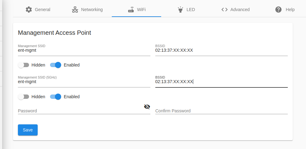
The Manangement Network SSID and password can be configured on the WiFi settings page.
LEDs
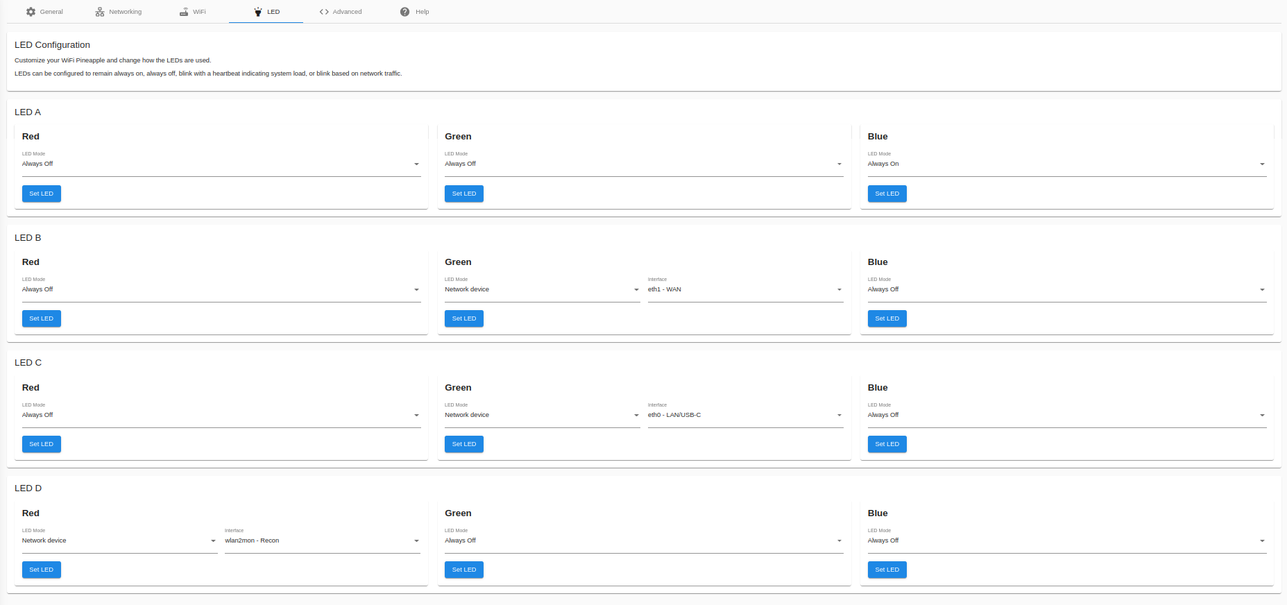
The WiFi Pineapple Enterprise has 4 LEDs, each of which have Red, Green, and Blue components which can be independently configured.
- Default Off
The LED remains off. - Default On
The LED is always on. - Heartbeat
The LED pulses regularly. The speed of the heartbeat is tied to the overall system load - the higher the CPU load of the Pineapple, the faster the LED will pulse. - Network device
Packets seen on a network device will cause the LED to blink.
Advanced
The Advanced tab shows options to change the current update channel for opting into Beta firmware releases. From here you can also access experimental features such as Censorship (hiding sensitive information in the UI) and Cartography (2D or 3D map of Recon data).

Alternative Updates
To participate in the WiFi Pineapple Beta Program, select the "Beta" channel from alternative updates. When new firmware is available, it will show up as an update in the beta channel!
Censorship Mode
Attempt to obfuscate MAC addresses, SSIDs, and other identifiable information in the UI. This option is predominately for streamers, educators, and anyone taking screenshots or making presentations using the WiFi Pineapple.
Remember - always be safe when broadcasting data which could be used to perform location lookups, such as MAC addresses and unique SSIDs. Always review your content before streaming and posting to make sure that no identifiable information is being shown despite censorship attempts.
Cartography Mode
Enable an optional view of network topology and connected clients, found in the Recon panel.
Hotkeys
Enable single-press hotkeys to navigate the web UI
Management Access
By default, the WiFi Pineapple allows access to the management interface (the WiFi Pineapple UI) and the SSH server by default on all interfaces.
To prevent users on the Open and EvilWPA networks, or other users on the WiFi and Ethernet networks the WiFi Pineapple is connected to, from accessing the management interfaces, they can be excluded here.
The management interfaces are always available via the USB-C connection and the Management wireless network.
Hostname
Change the default host name of the Pineapple device. This changes the name as shown in the SSH and web shells, and the host name used in DHCP requests sent in WiFi Client mode or over USB Ethernet.
Help
The Help tab is split into 3 sub-pages: Help & Information, Diagnostics, and Licenses.
The Help & Information page offers links to more resources like this and Hak5 community outlets.

The Diagnostics tab lets you generate a convenient diagnostics file that can be used to help troubleshoot any issues you may be experiencing with your WiFi Pineapple.

3.9 Cloud C²
Connecting the WiFi Pineapple to Cloud C²
Cloud C²
Cloud C² makes it easy for pen testers and IT security teams to deploy and manage fleets of Hak5 gear from a simple cloud dashboard.
Cloud C² is a self-hosted web-based command and control suite for networked Hak5 gear that lets you pentest from anywhere.
Linux, Mac and Windows computers can host the Cloud C² server while Hak5 gear such as the WiFi Pineapple, LAN Turtle and Packet Squirrel can be provisioned as clients.
Connecting to Cloud C²
Once you have Cloud C² installed and configured, adding a WiFi Pineapple to your server is simple!
- Create a device in your Cloud C² instance following these steps
- Download the device configuration file
- Navigate to "Settings" on the WiFi Pineapple
- Click the "Choose File" button in the Cloud C² card
- Upload your configuration file

WiFi Pineapple and Cloud C²
Once connected to a server, the Cloud C² service takes over most configuration and operation of the WiFi Pineapple.
Typical operations such as starting, stopping, and viewing recon scans, configuring filters, etc, are managed centrally by the Cloud C² server, and the local WiFi Pineapple UI is paused. The Cloud C² alert on the WiFi Pineapple allows for basic network configuration.

Should you find it necessary to make changes to the WiFi Pineapple locally, the UI can be re-enabled by the "Access UI" button.
[!CAUTION] Warning - The Cloud C² server will overwrite some configuration options, such as the PineAP and Recon Scan controls. Local control of the WiFi Pineapple while connected to Cloud C² should only be used for configuration changes that cannot be made remotely.
Disconnecting from Cloud C²
Your WiFi Pineapple can be unsubscribed from Cloud C² by clicking the "Remove Configuration & Reboot" button.
If you are in Local UI Bypass mode, it can be unsubscribed by navigating to "Settings" and using "Remove Configuration File" in the Cloud C² card.

3.10 Developer Resources
The WiFi Pineapple developer documentation, for things such as Rest API usage, Python API usage, Module development and more is currently available on GitHub.
Soon, they will be transferred to new sections here.
3.11 Contributing to the Module Repository
As mentioned in the WiFi Pineapple Mark VII Modules documentation, part of the process is forking and cloning the WiFi Pineapple Modules Git Repository. Once you have developed your module idea, you are encouraged to contribute to this repository by submitting a Pull Request with your module!
Reviewed and Approved pull requests will add your module to the WiFi Pineapple's module download site, where they will be able to be downloaded directly from the WiFi Pineapple management interface.
4. WiFi Basics, Radios, Antennas & 802.11 Frame Mechanics
4.1 Introduction to WiFi
In order to get the most out of the WiFi Pineapple, it’s best to have a basic understanding of some WiFi principals. This will lay the foundation to mastering the PineAP Suite – the WiFi sniffing and injection engine at the core of the WiFi Pineapple. Armed with this knowledge you’ll be equipped to execute a responsible and successful wireless audit by following our recommended wireless auditing workflow.
The purpose of this section is not to be all encompassing on the low level operation of the IEEE 802.11 specification lovingly known as WiFi, but rather a crash course in the absolute basics necessary for understanding the operation of PineAP and other WiFi Pineapple components.
4.2 Radios and Chipsets
Every WiFi radio is a transceiver, meaning it can transmit (TX) and receive (RX) information. Not every radio is created equal, however, as their capabilities may differ significantly. Software support in particular may inhibit an otherwise fine bit of silicon. In particular, modes of operation may be restricted either by hardware or software.
For the most part chipsets from Atheros and Mediatek have excellent support, with a few Ralink and Realtek chipsets having made a name for themselves in the infosec community as well. Radio chipsets typically interface with a computer over a bus like PCI or USB. A WiFi radio is often called a wireless network interface controller (WNIC or Wireless NIC).
On the other hand a SoC (System on a Chip) is a special WiFi chipset which combines the radio with its own CPU. WiFi SoCs, unlike typical x86-based PCs, traditionally run MIPS or ARM based CPUs. While lower in clock speed than their PC counterparts, they’re specifically optimized for high performance networking. The WiFi Pineapple Mark VII is based on Mediatek MT7601U and MT7610U chipsets.
4.3 Stations and APs
Technically speaking in regards to the architecture of any wireless network, each component is referred to as a station (STA). There are two categories of stations in an infrastructure mode WiFi setup — the base station (access point) and station (client). Be aware of this terminology as it may come up in other programs and documentation. Generally the WiFi Pineapple will refer to base stations as their more common name, access point or simply AP, and stations as clients or client devices.
4.4 Transmit Power
There are four aspects which influence the overall transmission power of a WiFi radio. The first in the chain is what’s being transmitted from the chipset or SoC natively. This is typically around 20 dBm or 100 mW and is often expressed in the operating system as txpower.
Next is any given amplifier which will boost the source signal before it reaches the antenna. This additional element to the chain is not necessarily integrated with the SoC, and thus may not reflect the actual txpower determined by the operating system.
The final part of the chain is the antenna, which offer the gain as rated in dBi. Additionally, higher gain antennas may be equipped, with 9 dBi being a common size for a standard omnidirectional antenna.
The total output power of this chain is expressed as EIRP, or equivalent isotropically radiated power. The EIRP is calculated by adding the output power of the radio (plus any amplification) in dBm with the gain of the antenna in dBi. For example a 24 dBm (250 mW) radio with a 5 dBi antenna will have a total output power of 29 dBm (800 mW).
Local regulations will determine the maximum transmission power of any WiFi equipment. For example in the United States the FCC states that a 2.4 GHz point-to-multipoint system may have a maximum of 36 dBm EIRP (4 watts) while point-to-point systems may achieve much higher EIRP.
4.5 Antennas
Antennas impact how a signal is transmitted or received.
An antenna can not create power, it can only shape the signal. An antenna offers signal gains in one aspect at the cost of other aspects.
Antennas are typically directional, where the signal gains are concentrated in one direction, or omnidirectional, where the signal is optimized for reception from all directions.
The WiFi Pineapple ships with standard omnidirectional antennas. These are the most appropriate for typical use cases where the goal is to detect access points and clients in the surrounding area.
Antenna Gains
Antenna gains are typically measured in dBi, or "dB over isotropic", a theoretical perfect antenna with no gain.
The higher the gain, the more the signal is impacted.
[!NOTE] Remember - more gain is not always better! There is always a trade-off with signal gain!
Omnidirectional Antennas
Omnidirectional antennas are typically found on access points, WiFi interface cards, and of course the WiFi Pineapple.
An omnidirectional antenna is designed to radiate in a roughly spherical shape.
As the gain of an omnidirectional antenna increases, the horizontal coverage increases but the vertical coverage decreases.
[!WARNING] Excessively high gains on omnidirectional antennas can be detrimental! Above approximately 9dBi of gain, the vertical range of the antenna can become so limited that clients and access points more than a foot or two higher or lower than the device are invisible!
Directional Antennas
Directional antennas can be used to shape the signal in a specific direction. Typically directional antennas cover an arc measured in degrees.
Directional antennas can be useful for targeting a specific device or area, but often are not the best solution for general data gathering.
4.6 Channels and Regions
Radio spectrum is divided up into channels. In the 2.4 GHz spectrum there are 14 channels, with channels 1, 6, 11 and 14 being non-overlapping. As described above in terms of bandwidth, the first channel in the 802.11g protocol begins at 2.400 GHz and ends at 2.422 GHz for a total bandwidth of 22 MHz. The first channel is then described as being centered at 2.412 GHz.
Channel availability is determined by region, with North America only having legal use of channels 1-11 while Europe and most of the world may use channels 1-13. Japan is special and gets access to all of the channels including 14 all to itself.
The 5 GHz spectrum is much more complicated in regards to bandwidth and channel availability by region with further restrictions on indoor/outdoor use. In the United States the FCC designates U-NII (Unlicensed National Information Infrastructure) bands 1-3 available, with 45 channels in total operating in 20, 40, 80 and 160 MHz bandwidth.
The WiFi Pineapple Mark VII operates in the 2.4 GHz band, with optional support for 5GHz operation using a supported USB WiFi device, while the WiFi Pineapple Enterprise operates in both the 2.4 and 5 GHz bands.
It’s also important to note that similar to modes of operation, a radio can only occupy one channel at a time. For this reason channel hopping is necessary in order to obtain a complete picture of the given spectrum. When performing a Recon scan, the WiFi Pineapple will switch one of its radios into monitor mode to passively listen on a channel. The radio will take a moment to note any data of interest on each channel before moving on to the next.
Further information on WiFi channels, their regulatory domains, and how they are mapped, can be found on resources such as Wikipedia.
4.7 Protocols
There are several WiFi protocols known by their letter designated IEEE 802.11 specifications, such as 802.11a, 802.11b, 802.11g, 802.11n, and 802.11AC. The differences are related to frequency (aka band or spectrum), data rate (aka throughput or transfer speed), bandwidth, modulation and range.
Bandwidth is often confused with data rate. While there is often a correlation between greater bandwidth and greater data rate, in terms of radio the bandwidth refers to the difference between the upper and lower frequencies of a given channel as measured in hertz. For example, with the 802.11b and 802.11g protocols the first channel will have a lower frequency of 2.400 GHz and an upper frequency of 2.422 GHz for a total of 22 MHz bandwidth, however the 802.11g protocol uses a more advanced encoding scheme allowing for significantly faster data rates in the same amount of bandwidth.
Modulation also affects data rate, with the most common modulation types being OFDM or Orthogonal frequency-division multiplexing and QAM or Quadrature Amplitude Modulation. In addition to being a mouthful, these are digital encoding techniques used to cram a lot of data on a small amount of spectrum. Typically newer 802.11 WiFi standards offer either improvements to the encoding scheme, or entirely new encoding schemes.
802.11a and 802.11b were the first mainstream WiFi protocols, introduced in 1999. 802.11a operates in the 5 GHz band with speeds up to 54 Mbps while 802.11b operates in the 2.4 GHz band with speeds only up to 11 Mbps. Today, these networks are more rare to find, though when they are it’s typically indicative of aging infrastructure.
Modern networks are usually 802.11n and 802.11ac, with data rates as high as 1800 Mbps, though typically lower speeds are actually observed. As the WiFi standards evolve and new products make their way into the marketplace, the common devices evolve.
Typically older devices are still able to use more modern access points via backwards compatibility: An 802.11n device can typically connect to an 802.11ac access point, but will only be able to do so at 802.11n speeds. Not all newer standards are backwards compatible with all devices, however.
4.8 Modes of Operation
Most commonly a WiFi radio will operate in one of three modes: Master, Managed, or Monitor. Additional possible modes (including ad-hoc, mesh, peer-to-peer, and repeater) and are both less common and outside the scope of this quick guide.
An Access Point (or simply AP) will operate in Master Mode while client devices operate in Managed Mode. Monitor mode, sometimes called RFMON for Radio Frequency MONitor, is a special mode that allows the radio to passively monitor all traffic in the given area, and requires special support in the drivers and firmware of the wireless device.
Keep in mind that not all radios have each of these capabilities and some radios have drivers that can only operate in one mode at a time.
4.9 Logical Configurations
WiFi networks can operate in a number of configurations, from point-to-point, point-to-multipoint, and multipoint-to-multipoint.
Point-to-point is simply a network of two. Multipoint-to-multipoint is where any node of the network can communicate with any other and is often called an ad-hoc, peer-to-peer or mesh network.
The most common configuration is point-to-multipoint, where a central access point is host to numerous client devices. This is also known as Infrastructure mode. An example of which might be a wireless router in your home with several laptops, phones, game consoles and the like connected. For the most part, this is the configuration we will be focusing on with the WiFi Pineapple.
4.10 MAC Addresses
Often called a physical address (PHY addr), the Media Access Control address (MAC address) is a unique identifier assigned to each Network Interface Controller (NIC). Typically this address is “burned” into the ROM of the network interface hardware, though often it may be changed via software.
MAC Addresses are formed by six sets of two hexadecimal digits (octets), typically separated by a dash (-) or colon (:) and may be either universally or locally administered. For example, 00:C0:CA:8F:5E:80.
Universally administered MAC addresses are unique to each network interface manufacturer. The first three octets represent the manufacturer or vendor as its Organizationally Unique Identifier (OUI). In the example above, 00:C0:CA represents the OUI for ALFA, INC – a popular Taiwanese WiFi equipment maker. OUIs are assigned by the Institute of Electrical and Electronics Engineers, Incorporated (IEEE). The vendor of any particular OUI may be determined by checking the IEEE MAC database, or the Wireshark OUI Lookup Tool. A database of OUI ranges is included in the WiFi Pineapple to display the manufacturer of devices.
Locally administered MAC addresses are typically assigned by the network administrator, replacing the universally administered address burned into ROM. For example, one may set their MAC address to DE:AD:BE:EF:C0:FE. This is sometimes called MAC spoofing.
4.11 Broadcast and Multicast MAC Addresses
Often with WiFi networks it is necessary to transmit the same bit of information to all stations. To facilitate this, the WiFi specification includes a special broadcast address. Expressed as the MAC FF:FF:FF:FF:FF:FF, transmissions destined to this address are meant for all stations in the vicinity.
While normally a WiFi interface is only concerned with traffic to and from its own MAC address, the default behavior is to also listen for messages bound to the broadcast address. An example of which is a beacon – a frame which advertises the presence of an access point. A beacon sent to broadcast will be “seen” by all stations in the area.
Similarly, a multicast address is a special type of address which operates like a broadcast address for the most part. Multicast addresses are used to set groups of devices which must communicate to many devices simultaneously, or special services such as mDNS and other service discovery protocols.
4.12 SSIDs
If you’ve been using WiFi for a while – and if you’re reading this we'll assume you have been – you’ve undoubtedly run across the term SSID. It’s the human readable “network name” associated with a WiFi Network – like “Joe’s Coffee” or “LAX Airport Free WiFi” or depending on your apartment building, perhaps a lewd comment directed toward neighbors. This “network name” is known as the Service Set Identifier. It can be up to 32 characters long and may identify either a Basic or Extended Service Set.
The majority of WiFi networks are Basic Service Sets (BSS). That is to say a single access point with multiple connected clients – be it laptops, tablets, gaming consoles or IoT coffee makers. Every station (both clients and AP) in the BSS are identified by a Basic Service Set Identification (BSSID). The BSSID is derived from the access point’s MAC address. Specifically the MAC address of the wireless NIC as the access point may also have an Ethernet Network Interface Controller with its own unique MAC address.
Extended Service Sets are larger WiFi networks whereby multiple access points, each with their own BSSID, all share the same SSID or “network name”. For instance a college or corporate campus may require many access points to cover the entire property. In this case the SSID is called an ESSID for Extended Service Set Identification, which facilitates client roaming.
A wireless client considers any access point with the same SSID to be part of the same network, and may choose to connect to any of the available APs. This forms some of the fundamental basis of the Evil WPA Twin attack.
4.13 802.11 Frame Types
WiFi frames come in three types, each containing several subtypes; control frames, data frames and management frames.
Control frames simply allow data exchange between stations, with Request to Send (RTS), Clear to Send (CTS) and Acknowledgement (ACK) frames facilitating communication with as little loss as possible. Frame loss is in inherent part of WiFi and control frames are intended to best coordinate shared usage of the available spectrum.
Data frames constitute the majority of WiFi communication, with the payload or frame body containing the actual TCP, UDP, or other packets. Since the basic data frame has a limit of 2312 bytes, the actual packets may be broken up into many fragments.
Management frames enable WiFi maintenance, such as advertising the presence of an access point as well as connecting to or disconnecting from such access point.
4.14 802.11 Frame Structure
The meat and potatoes of WiFi. Essentially everything transmitted by a wireless NIC comes in the form of a frame. They are the basic unit of most digital transmissions, and surround or encapsulate packets.
Frame Structure
A typical WiFi frame is broken up into several sections, consisting of a MAC header, payload and frame check sequence
The MAC header contains a Frame Control Field which includes, among other things, the 802.11 protocol version and frame type. Address fields including the BSSID, source and destination are also part of this section.
The Payload or frame body contains the actual information (typically a data packet) of either a management or data frame.
The Frame Check Sequence (FCS) concludes the frame with a cyclic redundancy check (CRC) sum of the MAC header and payload. This is used to verify the integrity of the frame and is essential to fault tolerance.
4.15 Management Frames
To enable the joining and leaving of a Basic Service Set, management frames contain subtypes such as beacon, probe, association, and authentication.
Beacon frames come in only one variety, and advertise the presence of an access point. They contain everything a client needs to know about a network in order to connect, including the SSID, supported data rates, protocol and other parameters pertinent to the APs modulation. Access points regularly transmit beacons, typically several times per second, to the broadcast address.
Beacon frames are essential for network discovery. When a client passively scans for nearby access points, it does so by listening for beacon frames. Typically this is done in conjunction with channel hopping, whereby a client will listen on each channel for a brief period before moving on to the next.
Probe frames further network discovery and come in two variety, probe requests and probe responses. Probe requests are transmitted by clients seeking access points. Probe responses are the access point’s replies to these client requests.
When a probe request is transmitted by a client seeking an access point, this is considered active scanning. The client will transmit to the broadcast address either a general probe request or a directed probe request. The former simply asks “what access points are around” while the later specifies the particular SSID for which the client seeks.
The probe response includes all of the basic information about the network also included in the beacon frame.
Association frames come in five forms: the association request, association response, reassociation request, reassociation response, and disassociation. Respectively, these can simply be thought of as “I’d like to be friends”, “Ok, we will/won’t be friends”, “Remember me, I’m your friend”, “I do/don’t remember you” and “Get lost, friend”.
Similar to probe frames, the requests are transmitted by clients while the responses by access points. Disassociation frames in particular are sent by any station wishing to terminate the association. This is the graceful way to ending an association, giving the station a heads up that the conversation is over and allowing it to free up memory in the association table.
Authentication frames are similar to association frames in that they enable the relationship between client and access point to form. Originally only two security states existed for WiFi – Open or Wired Equivalent Privacy (WEP). The later is a broken and deprecated technology which has given way to more secure schemes such as WPA2 and 802.1X. For this reason authentication frames are almost always open, regardless of the security state, with the actual authentication handled by subsequent frames after the station is both authenticated and associated. In this case a client will send an authentication request with the access point sending an authentication response.
Deauthentication frames act similar to disassociation frames and are sent from one station to another as a way to terminate communications. For example, an access point may send a deauthentication frame to a client if it is no longer authorized on its network. When this unencrypted management frame is spoofed by a third party, the technique is often called a deauth attack.
4.16 Frame Injection
It should be apparent that much of WiFi operation relies on trust, particularly with regard to the validity of source and destination addresses. Given these values may be spoofed, it’s with the technique of frame injection that various attacks may be carried out.
Simply put, frame injection is the process of transmitting any WiFi frame desired, regardless of an association with any station. One example may be a beacon frame injected into the air with specific values set to aid the penetration tester.
Another example may be a deauthentication frame with a spoofed source and destination address. Not all radios and software support this ability. This technique is leveraged by the PineAP suite for a number of attacks using the WiFi Pineapple hardware.
4.17 Association and State
With an understanding of management frames, we can explore the states of association. In this example we’re looking at the steps necessary for a connection between a client and an open access point.
In the Unauthenticated and Unassociated state, the client seeks the access point. This is either done passively by listening to the broadcast address for beacon frames transmitted by the access point, or actively by transmitting a probe request.
Once the client has received either a probe response or beacon frame from the access point, it can determine its operating parameters (channel, protocol, data rate, modulation details, etc). The client will then send the access point an authentication frame requesting access. In the case of an open network, the access point will send the client back an authentication frame responding with a success message.
Now the client is Authenticated and Unassociated. Next the client will send the access point an association request. The access point will reply with an association response.
If successful, the client will now be Authenticated and Associated. At this point any additional security, such as WPA2, may be negotiated. Otherwise in the case of an open network, the usual first network interactions will occur. These are the same as in wired networks, and typically begin with obtaining IP address information from a DHCP server on the host network.
In the case of the WiFi Pineapple, the client network is open and the DHCP server will assign new clients with addresses in the 172.16.42.0/24 range
5. FAQs, Troubleshooting, Upgrades & Maintenance
5.1 Establishing an Internet Connection
- Configuring a Client Mode Connection
- Configuring ICS on Linux
- Configuring ICS on Windows
- Configuring a USB Ethernet Adapter
5.2 Configuring a Client Mode Connection
You may use a radio on the WiFi Pineapple to connect to an external WiFi network, for getting an internet connection or for communicating with other devices on that network.
To configure a client mode connection, navigate to Settings > Networking in the User Interface. You will be presented with a card labelled Wireless Client Mode.

[!WARNING] While you may select other wireless interfaces for Client Mode, you are greatly recommended to use wlan2, as it is dedicated for Client Mode.
After clicking the Scan button, a list of surrounding wireless networks will be listed for you. Select the SSID you wish to connect to, and enter the SSID or PSK if required. Click Connect to start a connection.

If the connection is successful, you will be presented with the associated SSID and an acquired IP, if DHCP is enabled on the network.

[!NOTE] If you are required to set a static IP address, you must do so via the command line. Press the backtick (`) on your keyboard to open a Web Terminal.
[!NOTE] The Wireless Client Mode configuration is automatically saved, and an attempt to reconnect will happen every boot, automatically.
5.3 Configuring ICS on Linux
ICS, or Internet Connection Sharing, can be used to share internet from your computer to the attached WiFi Pineapple, over it's USB-C Ethernet connection.
On Linux, this is easy to accomplish with the use of the WiFi Pineapple ICS Script, referred to as wp7.sh. It is a shell script that will guide you through the ICS setup process.
Getting Started
Start by opening the Terminal emulator for your Linux distribution. On Ubuntu, Gnome Terminal can be found by searching for "Terminal".
Once the Terminal is open, get the WP7.sh script, and mark it as executable with chmod.

Once you've done that, execute the script as root, with sudo ./wp7.sh.

Guided Setup Mode
In this mode, the ICS script will try to automatically determine which interface is the WiFi Pineapple, and what your current network settings are. To do this, press G on your keyboard and follow the on-screen instructions.

Now you can press C to connect.
[!NOTE] Note that you may need to toggle the USB-C Ethernet interface in your Network Manager before the script will detect your WiFi Pineapple.
5.4 Configuring ICS on Windows
On Windows, Internet Connection Sharing is achieved by using Window's "Network Sharing" feature, by sharing one internet-enabled interface to the WiFi Pineapples.
[!NOTE] The following guide is designed to work on Windows 11, although the same or similar steps apply to Windows 10/8.1/8/7 too.
Configuring the Internet facing interface
Start by opening the Network & Internet settings in the Windows settings application. Scroll down to Related settings and click More network adapter options.

In the new window, right-click the Internet facing adapter, and select "Properties". In this guide, the Internet facing adapter is the interface named Ethernet.
Once you're in the properties window, select the Sharing tab, and then check the box to allow other users to connect. Then, select the WiFi Pineapple adapter and click OK.

Next, configure the WiFi Pineapple adapter by right clicking and selecting "Properties". In the new window, select the text that says Internet Protocol Version 4 (TCP/IPv4) and select Properties.

Finally, set the adapters IP settings as follows:
- IP Address: 172.16.42.42
- Subnet Mask: 255.255.0.0
- Default Gateway: Blank
- Preferred DNS: 8.8.8.8
- Alternate DNS: 8.8.4.4

[!NOTE] You may set your own preferred and alternate DNS servers if desired, but Google's DNS is recommended.
After clicking OK to save the settings, your WiFi Pineapple will now be able to access the internet through the USB-C interface connected to your computer.

5.5 Configuring a USB Ethernet Adapter
Some USB Ethernet Adaptors are supported out-of-the-box. For a reference of supported adapter chipsets, look at the table below.
| Manufacturer | Chipset | Description |
|---|---|---|
| ASIX | AX88179 | ASIX USB2.0 Ethernet 10/100 |
| Realtek | RTL8152 | Realtek USB2.0 Ethernet 10/100 |
| Realtek | RTL8153 | Realtek USB3.0 Ethernet 10/100/1000 |
Installing kernel modules for other chipsets
If your USB Ethernet adaptor has a chipset that isn't listed above, it is possible that an available driver/kernel module is available for the WiFi Pineapple MK7.
You can check this by going to the WiFi Pineapple's Web Interface, and going to Modules > Packages, and searching for the name of your chipset.
5.6 Password Reset
You may reset a lost password by booting the device, then pressing and holding the reset button for approximately 10 seconds. Upon releasing the button, the device will reset the password, flash the LEDs as white, and reboot.
After the device reboots, you will be able to login with the password hak5pineapple. You are strongly advised to change this after logging in.
5.7 Factory Reset and Recovery
To restore your WiFi Pineapple back to a factory state, or to recover from a bad configuration, you can perform a Firmware Recovery.
The firmware recovery method consists of using the device bootloader to flash the stager.
Preparation
To begin, download the latest Stager file from the Hak5 Download Portal.

[!WARNING] For this procedure, it is important to download the special RECOVERY firmware — not the latest stable production firmware.
Once the recovery firmware has been downloaded, you may wish to verify the SHA256 sum of the downloaded file.
Using a paperclip, SIM card ejection tool or similar instrument, hold down the reset button while applying power to the WiFi Pineapple Enterprise. This may be achieved by plugging in the supplied power cable into the unit, or flipping the on/off switch on an attached power strip.
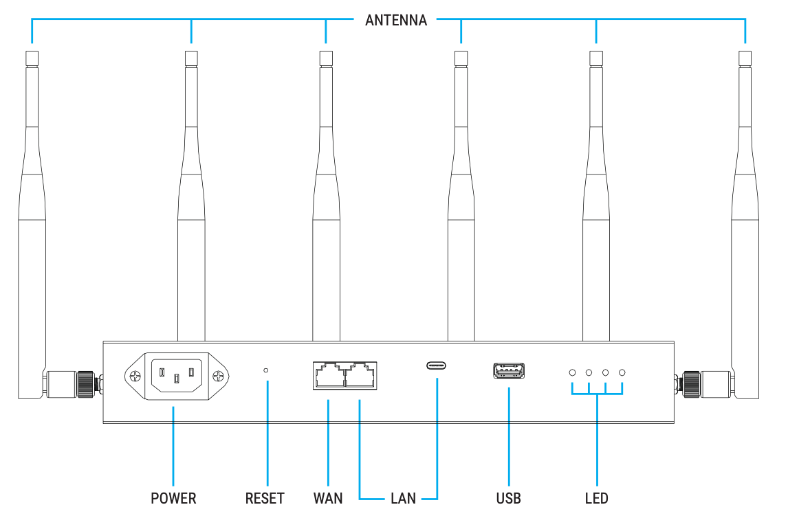
With the reset button held, the WiFi Pineapple Enterprise will show the following LED indications:
- Four white solid LEDs
- One blue solid LED
- One blue solid LED and one blinking red LED
Immediately after the red LED begins blinking, release the reset button.
The LED indication should remain with one LED solid blue, one LED blink RED, and two LED's off. If the status LED changes before the firmware recovery is uploaded from the web interface, disconnect the power and repeat the above process being sure to release the reset button immediately after the red LED begins blinking.
Assigning a Static IP Address
Linux
Assign the WiFi Pineapple's interface a static IP address of 172.16.42.42. More in-depth instructions can be found in the Linux Setup page.
Windows
Assign the WiFi Pineapple's interface a static IP address of 172.16.42.42. More in-depth instructions can be found in the Windows Setup page.
[!NOTE] New to static IP address assignments in Windows? Check this tutorial.
Uploading the Stager to the WiFi Pineapple
Once a static IP address has been assigned, open your browser and navigate to http://172.16.42.1. You'll then be greeted by a screen prompting you to upload a .bin image.
[!NOTE] Keep in mind the recovery page is on the standard HTTP port 80, not port 1471 like the normal WiFi Pineapple web interface.
If you have trouble reaching the WiFi Pineapple recovery page, make sure that:
- The WiFi Pineapple Enterprise is showing a single solid blue LED, and a single blinking red LED. If it is not, disconnect the power from the device and begin this process again.
- You have a static IP assigned to the network interface created when you plug in the WiFi Pineapple.
- You are attempting to navigate to http://172.16.42.1 on the standard HTTP port 80, and not port 1471 used by the WiFi Pineapple web interface.
If you are still having trouble, try opening an Incognito or Private window in your browser, then navigating to http://172.16.42.1:80. Sometimes a browser will cache the previous results and obscure the page.

Select Choose file and then select the downloaded stager file from earlier. After clicking Update firmware, the device will begin flashing.
[!CAUTION] Do not unplug the device. Doing so will potentially damage your device. It will automatically reboot once complete.
Once the process is complete, you will be able to set the device up again. See the Setup section for more details.
5.8 WiFi Pineapple Updates
Updating the firmware on the WiFi Pineapple
Getting Updates
When a new WiFi Pineapple update is available, you can automatically download and install it by navigating to the Settings > General page on the device:

Here you can check for new updates and automatically install them (standard), or install a locally downloaded firmware file, if you have downloaded the firmware from the download portal or been provided a firmware file.
Updating
Updating the firmware of your WiFi Pineapple will factory reset the device - you will need to perform the initial setup again, and any old recon data will be lost.
You should always download any recon scans before performing a system update.
Once the update begins, the LED of the device will flash alternating red and blue. An update typically takes five to ten minutes, do not unplug your device during the update process!
Once the update is complete, the device will reboot and enter setup mode. If the web interface does not automatically refresh, make sure that you are still connected to the WiFi Pineapple device, and navigate to http://172.16.42.1:1471 . If you were connected to the WiFi Pineapple via the management WiFi, you will need to connect either using USB-C or the setup WiFi networks.
The SSH host key of the WiFi Pineapple is dynamically generated on first boot - after upgrading your device, you will receive a SSH host key mismatch when connecting via OpenSSH, Putty, or other SSH clients. This is normal when upgrading, and you should remove the offending key from your client and accept the new key (however, in any other circumstances you should not accept new SSH keys from a host unless you have confirmed they have changed!)
5.9 WiFi Pineapple Beta Updates
The WiFi Pineapple has multiple update channels for its update mechanism. These channels allow you to specify what type of firmware release you want to use on your WiFi Pineapple.
Currently, there are two update channels:
- Stable
- Beta - Pre-release updates that may be unstable, but may also contain new bug fixes, features and more.
To manage your selected update channel, go to Settings > Advanced in the Web Interface.

Using the drop-down list and the Set Update Channel button, you'll be able to change the update channel. You may set the channel back to Stable at any time.
Once you've picked an alternative channel, go back to the Settings tab and Check for new updates. If an update is available, you will be presented with the option to update.

5.10 Compatible 802.11ac Adapters
The WiFi Pineapple Mark VII supports 802.11ac monitor and frame injection with a supported adaptor.
The WiFi Pineapple Enterprise comes equipped with 3 MT7612U 802.11ac capable radios, but you may add more via USB if desired.
| Adaptor | Chipset |
|---|---|
| Hak5 MK7AC Adapter | MT7612U |
| AWUS036ACM | MT7612U |
| EP-AC1605 V1 (V2 is incompatible) | MT7612U |
Installing drivers for other WiFi Adaptors
While the WiFi Pineapple has support for MT7612U and MT7601U devices out of the box, you can also install drivers for a wide range of other chipsets, such as other MT76-based devices, ath9k and ath10k devices, and some Realtek dongles.
To find drivers, you can use the Package Manager found in the Web Interface under Modules > Packages. Search for keywords related to the chipset in your adaptor.
More information about your specific adaptor can usually found with resources such as WikiDevi.