SDRLab H4M Pro (HackRF Pro R10C PortaPack) — Complete Guide
One-liner: The H4M Pro is the advanced flagship generation of the HackRF PortaPack ecosystem — powered by the redesigned HackRF Pro R10C RF core, a high-capacity user-replaceable 18650 lithium power subsystem, dual-side 4-port SMA antenna array, and a distinctive red-and-white QR pixel art acrylic sandwich enclosure.
Applicable Hardware: SDRLab H4M Pro (HackRF Pro R10C RF board mated with PortaPack H4M Pro display panel).
Target Audience: Advanced researchers, RF test engineers, and graduate telecommunication laboratories.
Reference Firmware: PortaPack-Mayhem v2.4.0 official release (dedicated hardware targethpro/ binary:firmware_hpro.bin).
Manual Version: 03 | Updated: 2026-10-03 | Platform: doc.yupitek.com (Official English Edition)
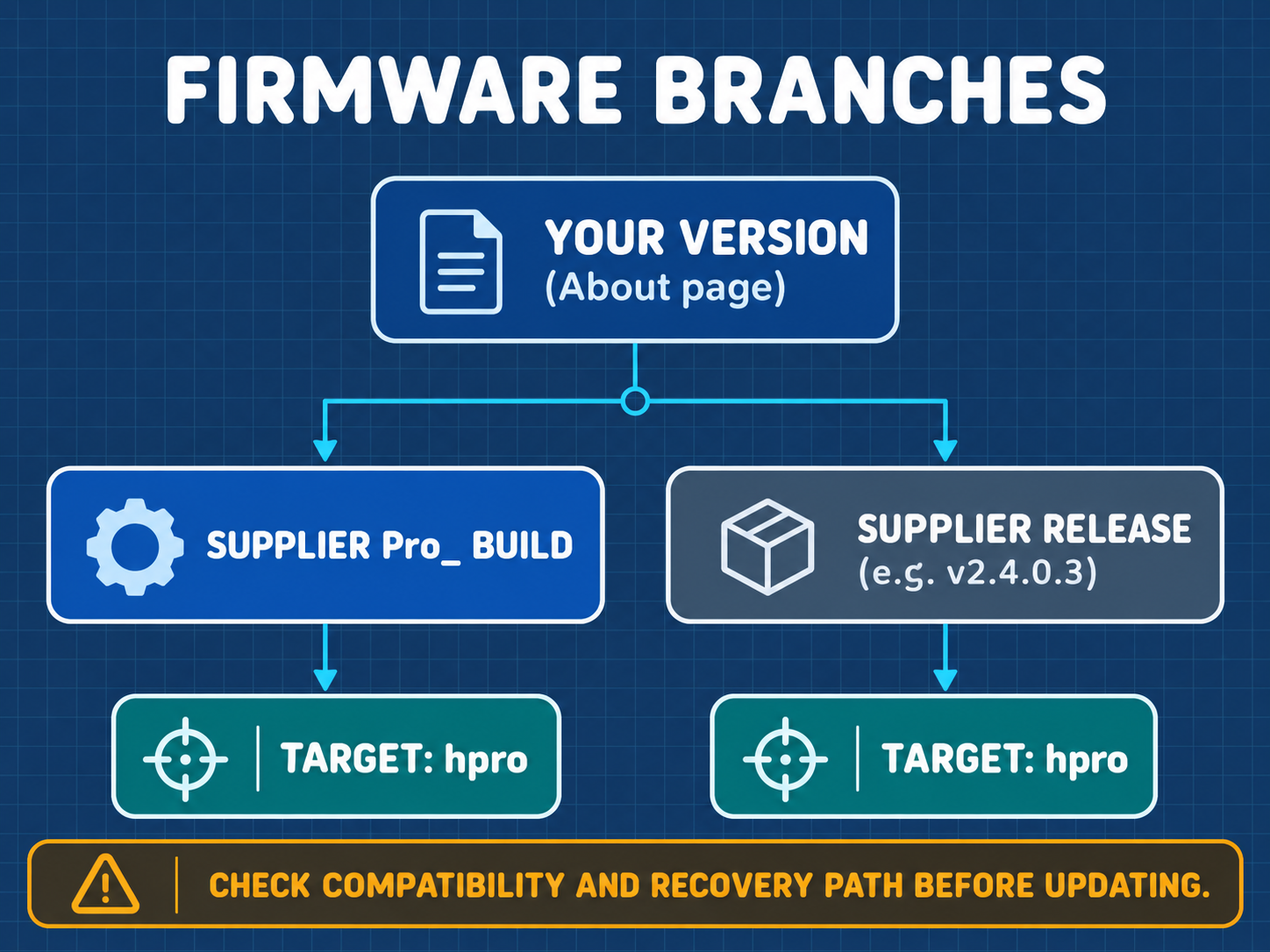
The SDRLab H4M Pro features dedicated hardware pinouts, power management, and clock circuitry that require the hpro firmware target (firmware_hpro.bin). Never flash standard HackRF One firmware (portapack-h1_h2-mayhem.bin or hackrf.bin) onto an H4M Pro, as doing so will disable power management and brick the device!
Table of Contents
- 00 Read Me First: 5 Safety Principles and Learning Roadmap
- 01 15-Minute Quick Start (First Success: Tuning FM Broadcast)
- 02 Hardware Anatomy and Control Interface
- 03 Bill of Materials and Required Equipment
- 04 Assembly, 18650 Battery, Charging, Boot, and Calibration
- 05 Preparing the microSD Card and Deploying Asset Packs
- 06 First Signal Reception: Public FM Broadcast (Detailed Tutorial)
- 07 Understanding Spectrum, Waterfall, Gain Staging, and Scanning
- 08 Connecting to a Computer (Tethered SDR Mode)
- 09 Elective Advanced Reception: APRS, POCSAG, BLE, and ADS-B
- 10 Laboratory Authorized Wired Capture, One-Shot Replay, and TX Experiments
- 11 Advanced Maintenance: Firmware Updates and DFU Recovery
- 12 Troubleshooting and Frequently Asked Questions (FAQ)
- 13 Core Technical Glossary and Concept Reference
- 14 Learning Verification Checklist and Standard Lab Worksheet
- Appendix A: Frequency Band Allocation and Station Query Guide
- Appendix B: Complete Hardware Accessory Specifications
- Appendix C: RF Power Budget and Attenuation Chain Calculation Worksheet
- Appendix D: Official Resources and Extended Reading
00 Read Me First: 5 Safety Principles and Learning Roadmap
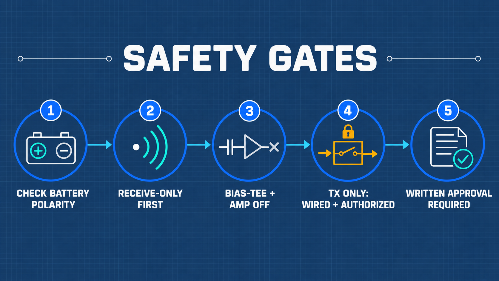
- Prioritize Pure Reception (RX-Only): Master signal observation, waterfall diagnostics, and digital demodulation before even considering transmission.
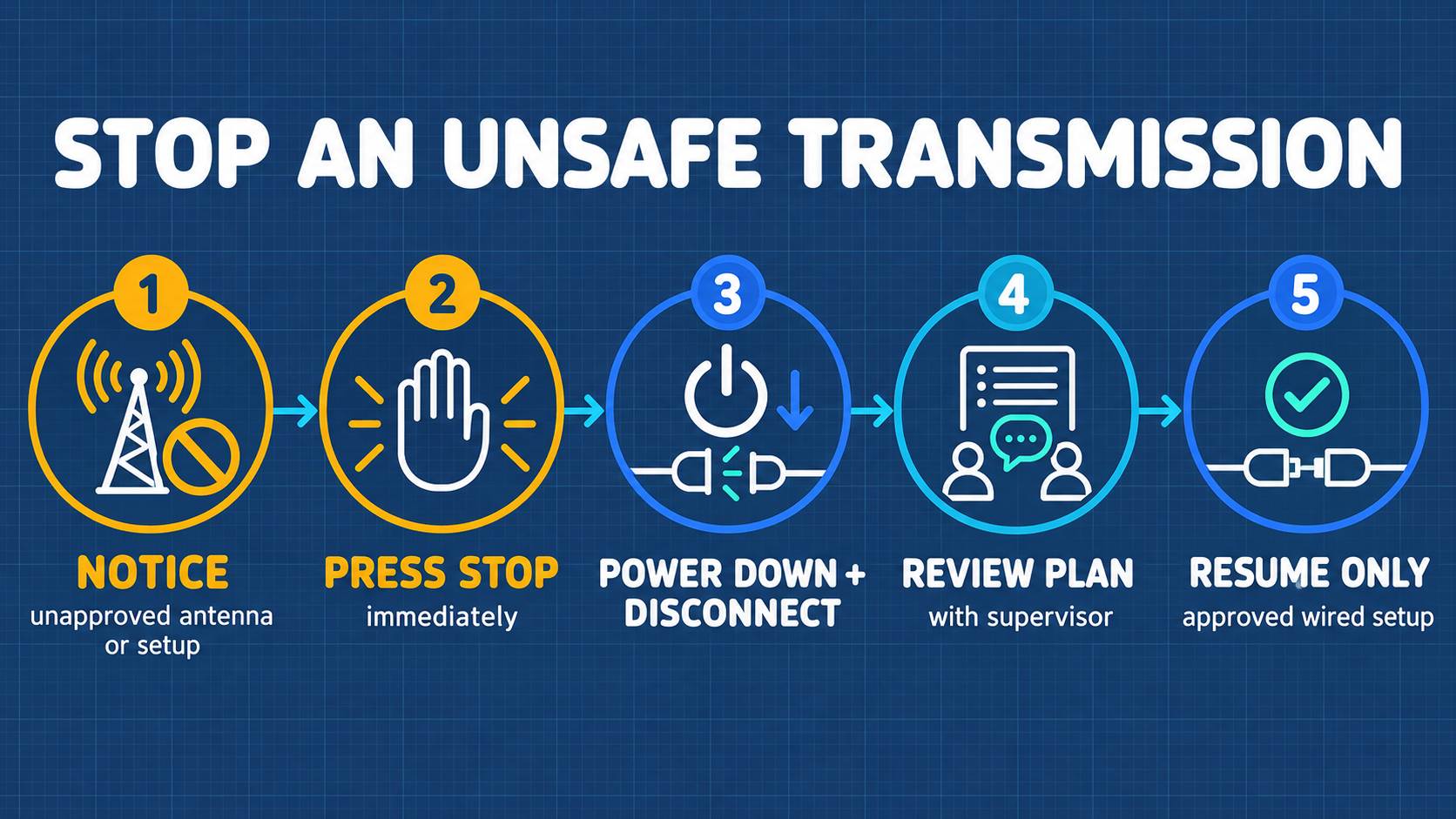
- Strict Wired Transmission Only: Over-the-air RF radiation without authorization is prohibited. All transmission experiments must take place across a closed 50 Ω coaxial network with written supervisor approval.
- Antennas Strictly for Reception: Never enable transmit modes while antennas are mounted.
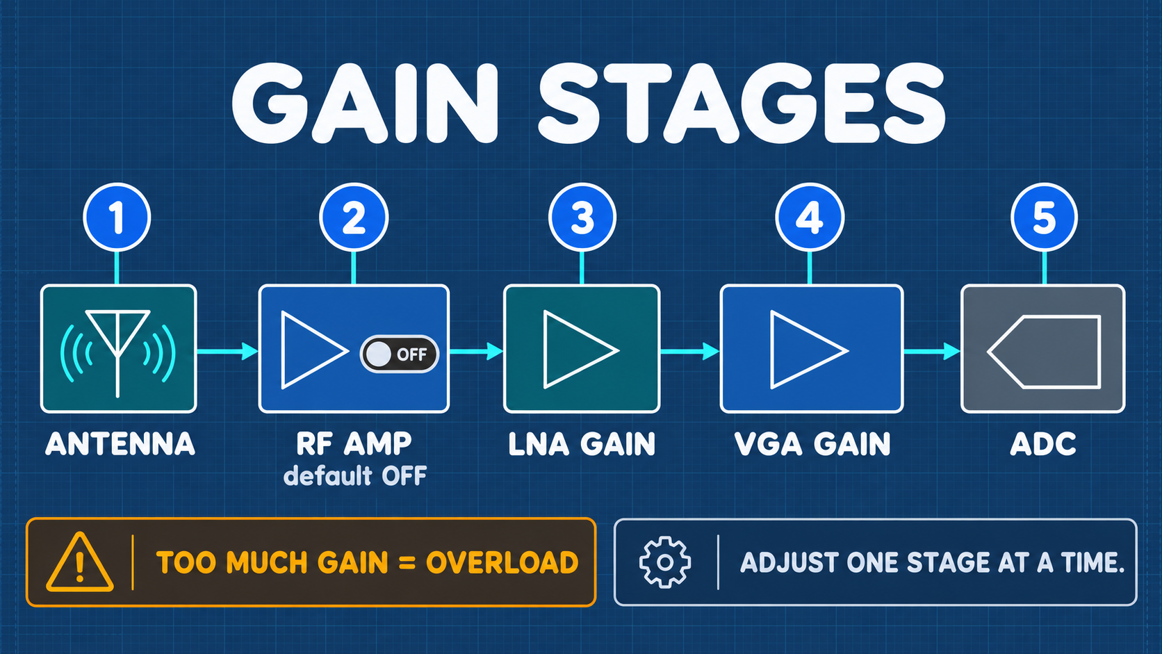
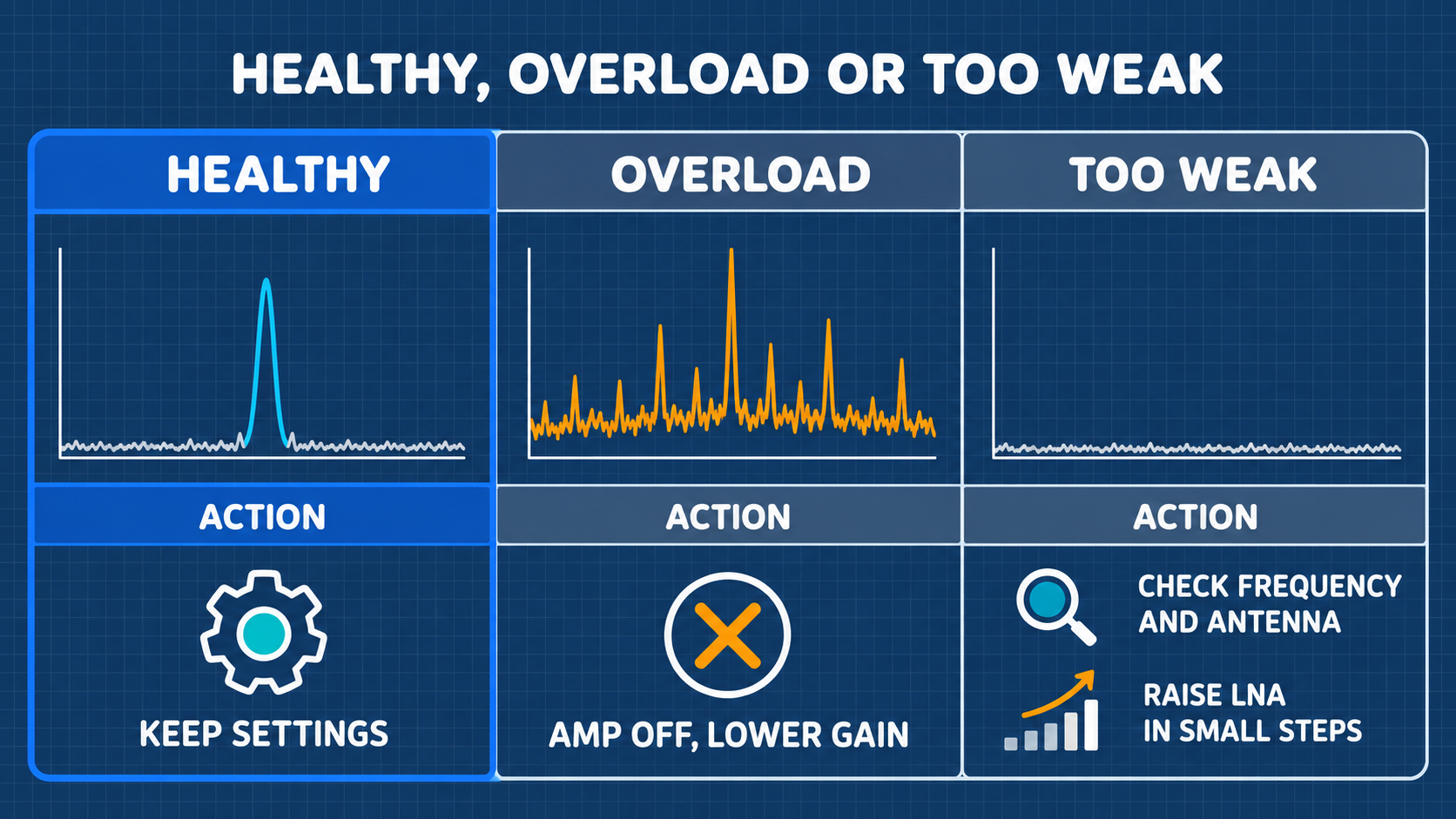
- Bias-Tee and RF Amp OFF: Prevent front-end LNA destruction by keeping phantom DC power and RF amplifiers disabled by default.
- Shut Down Immediately Upon Anomalies: If the 18650 battery compartment becomes unusually hot (> 45°C), immediately toggle the power switch off and remove the battery.
01 15-Minute Quick Start (First Success: Tuning FM Broadcast)
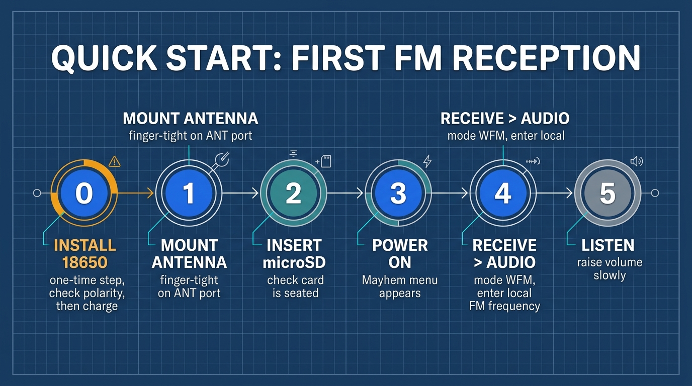
| Step | Core Action | Expected Result |
|---|---|---|
| Step 0 | Install single 18650 cell (confirm flat-top, positive terminal inward) | Secure battery fit, spring contact seated |
| Step 1 | Thread receiving antenna onto the primary ANT SMA port | Finger-tight mechanical coupling |
| Step 2 | Insert FAT32 formatted microSD card | Audible latch in card receptacle |
| Step 3 | Toggle master POWER switch to ON | Splash screen illuminates within 3 seconds |
| Step 4 | Enter Receive → Audio, set WFM, enter local frequency | Clear demodulated broadcast audio |
| Step 5 | Adjust volume smoothly via the large rotary knob | Audio streams via internal speaker |
02 Hardware Anatomy and Control Interface
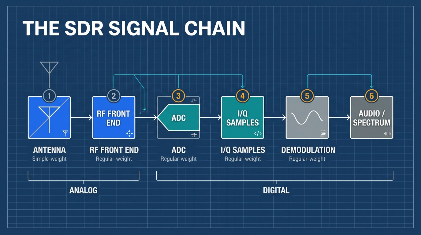
Two-Layer Architecture Overview
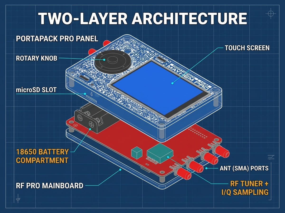
The H4M Pro adopts a ruggedized triple-acrylic sandwich design housing two primary interconnected circuit boards:
- Lower Tier — HackRF Pro R10C RF Core: High-frequency wideband transceiver circuit, featuring enhanced RF ground shielding, optimized differential trace matching, and dedicated TX/RX switching paths.
- Upper Tier — PortaPack H4M Pro Control Interface: Houses the 3.2-inch matte touchscreen, oversized industrial knurled rotary encoder, tactile lateral switches, audio codec, and the rear-mounted 18650 battery cradle.
Antenna Port Allocations (Dual-Side 2+2 Array)
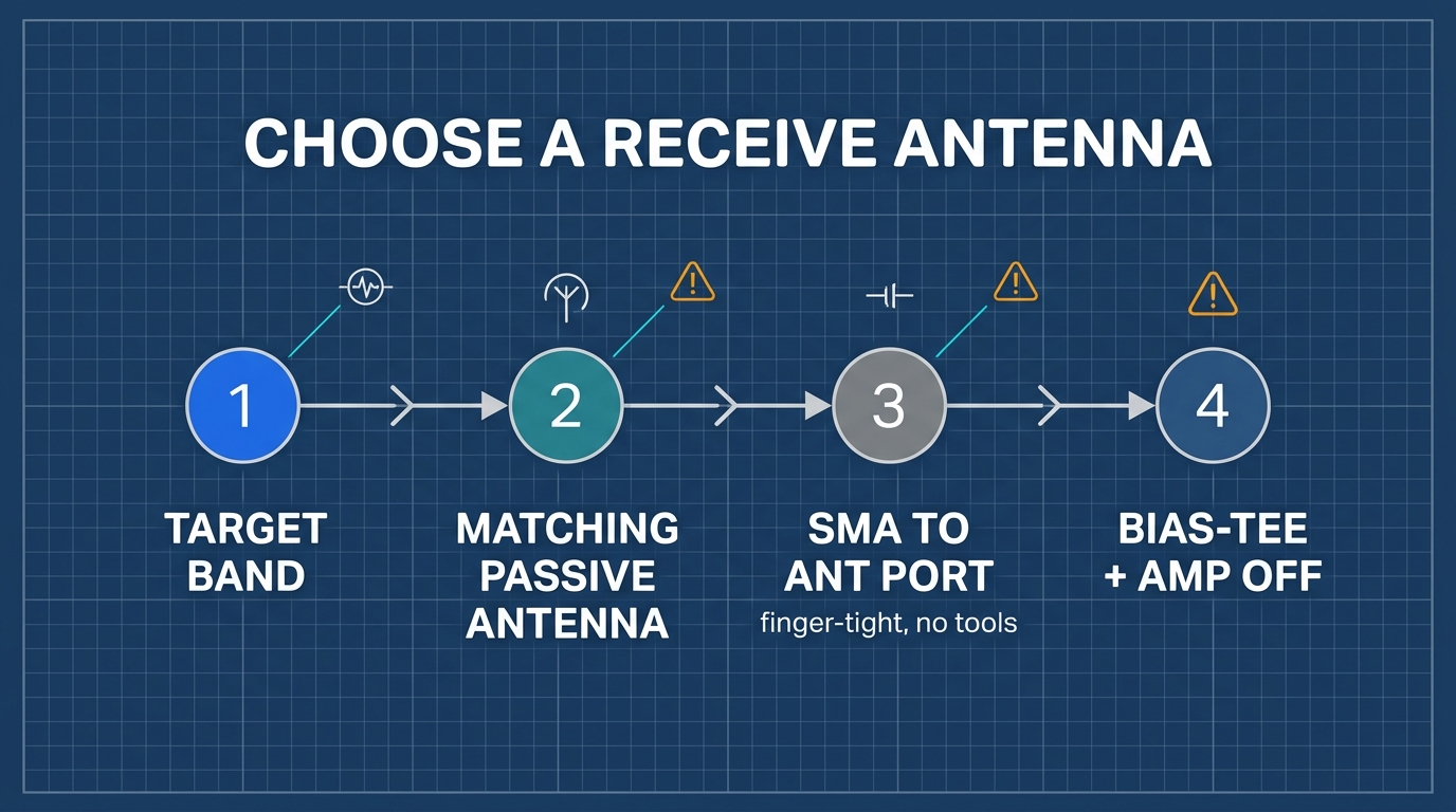
- Left Edge Ports: Primary
ANTtransceiver port (SMA female, 50 Ω) andCLK INclock reference port. - Right Edge Ports:
AUX / RX2auxiliary observation port andCLK OUTreference distribution port.
03 Bill of Materials and Required Equipment
1. Pure Reception Self-Prepared BOM
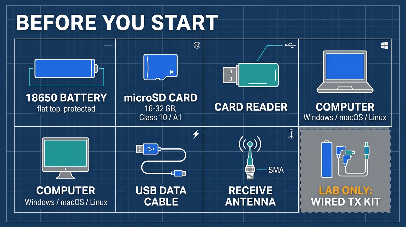
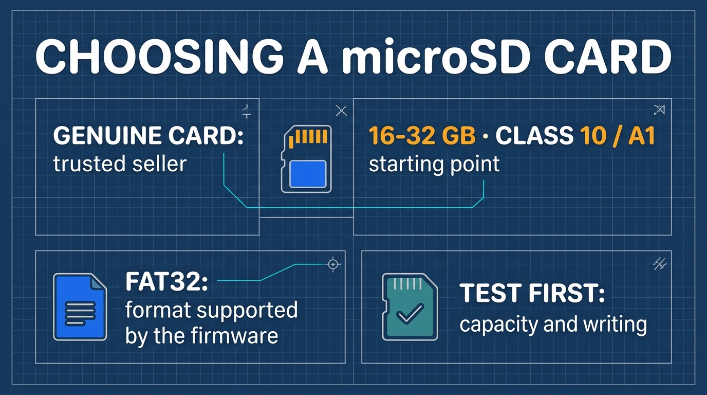
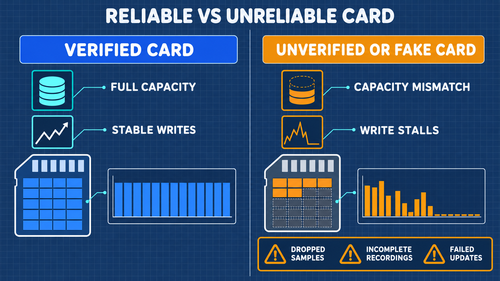
- MicroSD Card: 16 GB to 32 GB, Class 10 / A1 rated.
- 18650 Rechargeable Lithium-Ion Battery (Procured Separately):
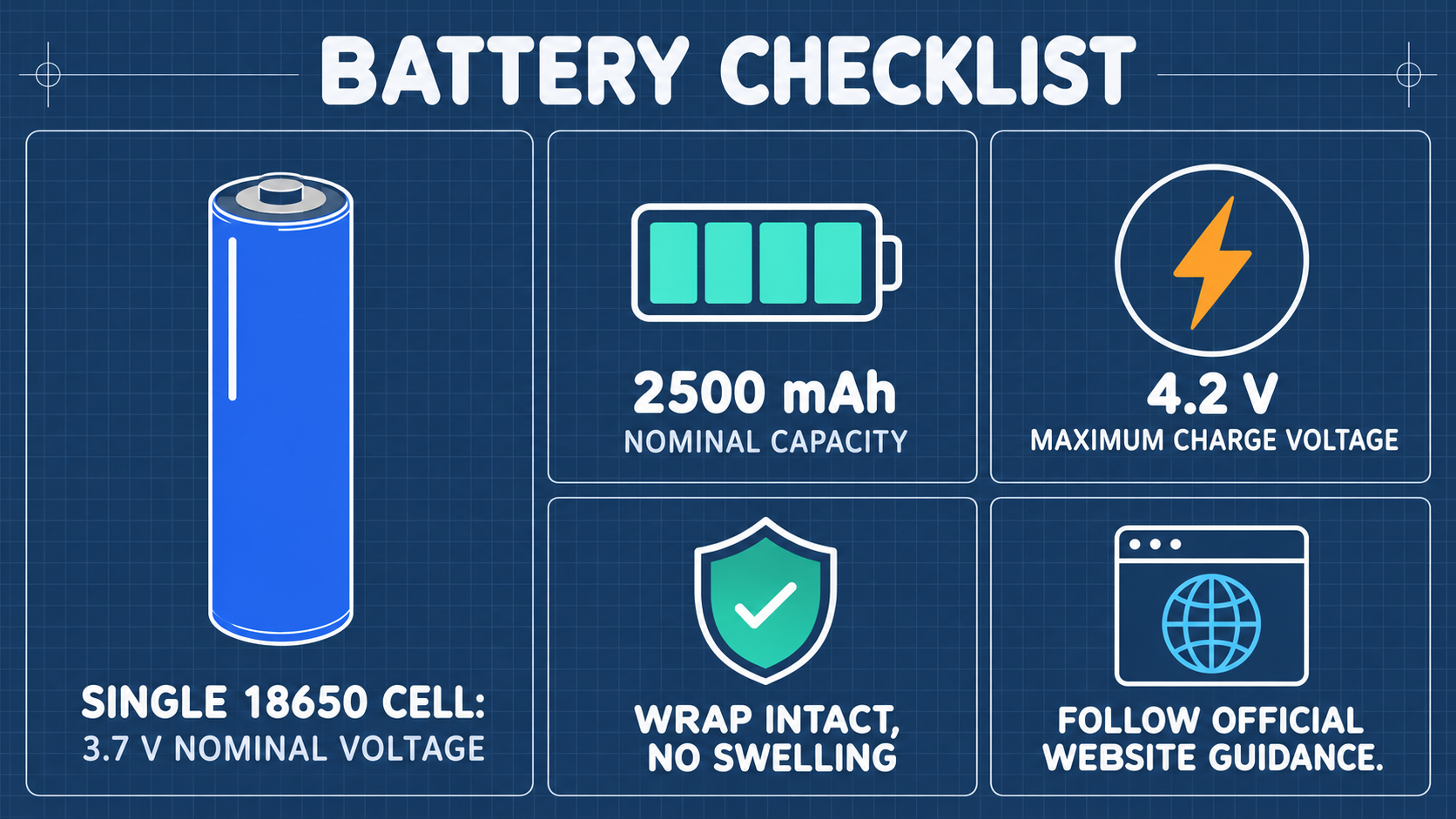
- Nominal Voltage: 3.7 V (Fully charged: 4.2 V)
- Recommended Capacity: 2,500 mAh to 3,500 mAh
- Form Factor: Flat-Top (Unprotected or slim-protected). Button-top cells will not fit into the battery clips!
2. Laboratory Wired RF Safety Kit
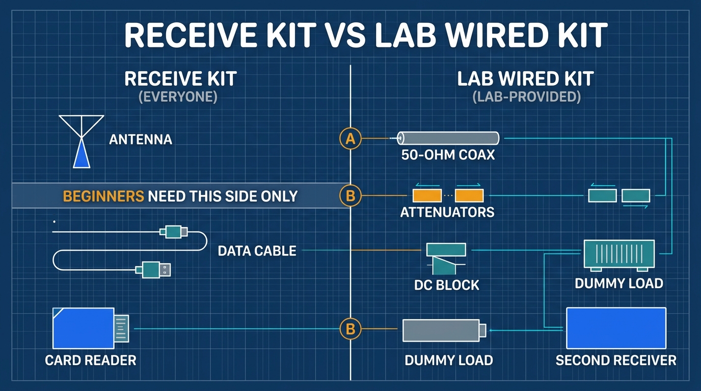
- Coaxial Attenuators: 50 dB total attenuation (30 dB + 20 dB, ≥ 2W, DC–6 GHz).
- DC Block: 10 MHz – 6 GHz, 50 Ω.
- 50 Ω RF Dummy Load: ≥ 2W, SMA Male.
3. Official Software Download Channels

- Official Pro Binary:
firmware_hpro.binor.ppfw.tartargeted forhpro. - SD Assets:
COPY_TO_SDCARD.zip(matching exact release version).
04 Assembly, 18650 Battery, Charging, Boot, and Calibration
4.1 Assembling HackRF Pro and PortaPack H4M Pro
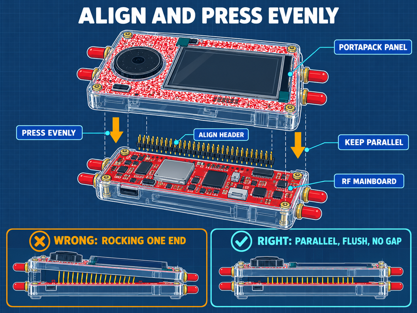
- Ensure the board interconnect headers (P20/P22/P28) align in parallel without bending pins.
- Fasten the four corner brass standoffs with even torque; do not over-tighten against the acrylic faceplate.
4.2 18650 Battery Installation and Polarity Rules
Installing the 18650 battery backwards will permanently damage the onboard power management IC and create a severe thermal runaway fire hazard!
- Negative Pole (-) Flat End: Must face the metal spring contact.
- Positive Pole (+) End: Must face the solid brass button terminal.
4.3 Charging, Holding Check, and Temperature Monitoring
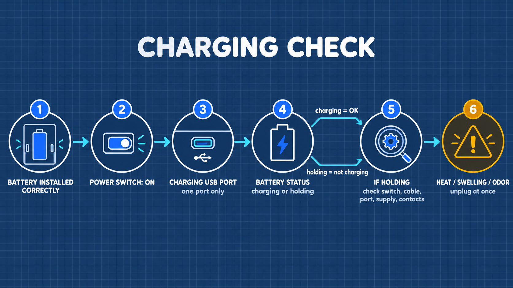
- Connect standard 5V/2A USB-C power adapter.
- Toggle the dedicated charging switch to enable charging. The charge status indicator illuminates red.
- When charge completes (indicator turns green/blue), perform a voltage holding check: status bar should display between 4.15 V and 4.20 V.
4.4 First Boot and Version Verification
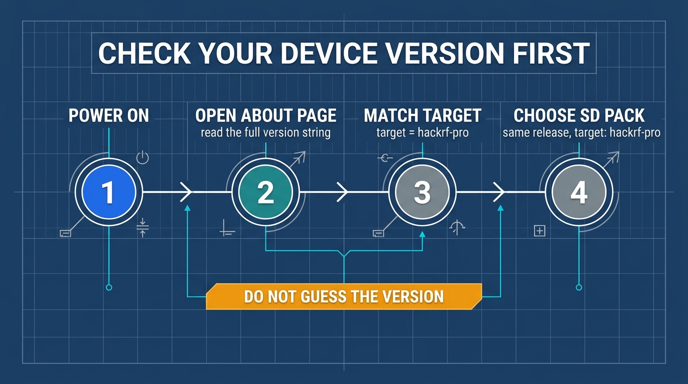
- Slide main power switch ON.
- Navigate to
Settings->About. - Verify that the hardware target string explicitly confirms:
target = hpro.
05 Preparing the microSD Card and Deploying Asset Packs
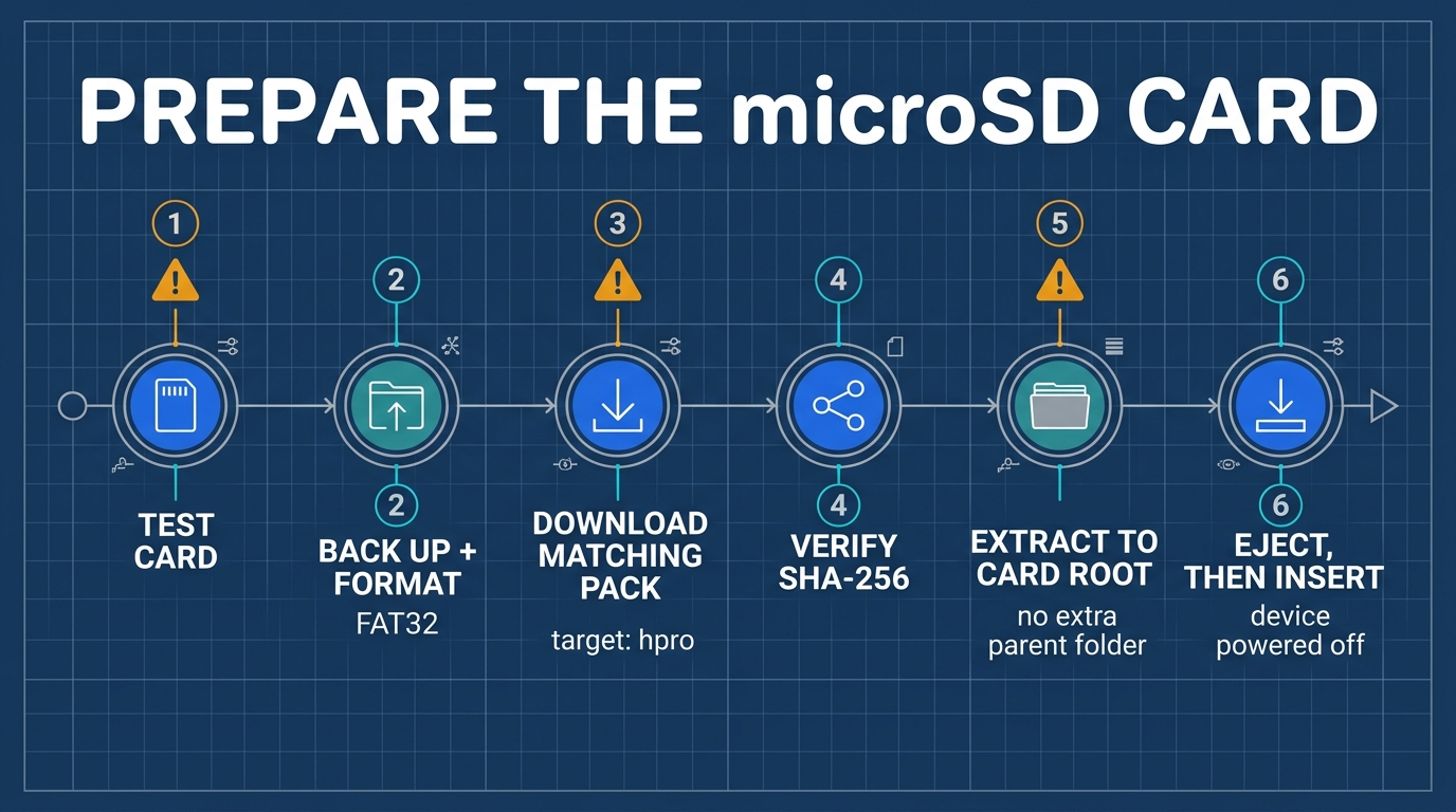
Format microSD card as FAT32, extract COPY_TO_SDCARD.zip to the root, and confirm folders APPS, FREQMAN, and SETTINGS are populated.
06 First Signal Reception: Public FM Broadcast (Detailed Tutorial)
- Connect wideband antenna to
ANTSMA port on the left edge. - Select Receive → Audio.
- Set
FREQto local FM station,MODtoWFM,BWto200k. - Adjust
LNAto24 dB,VGAto24 dB,AMPtoOFF. - Rotate knurled volume dial to enjoy clean broadcast audio.
07 Understanding Spectrum, Waterfall, Gain Staging, and Scanning
7.1 Spectrum and Waterfall Principles
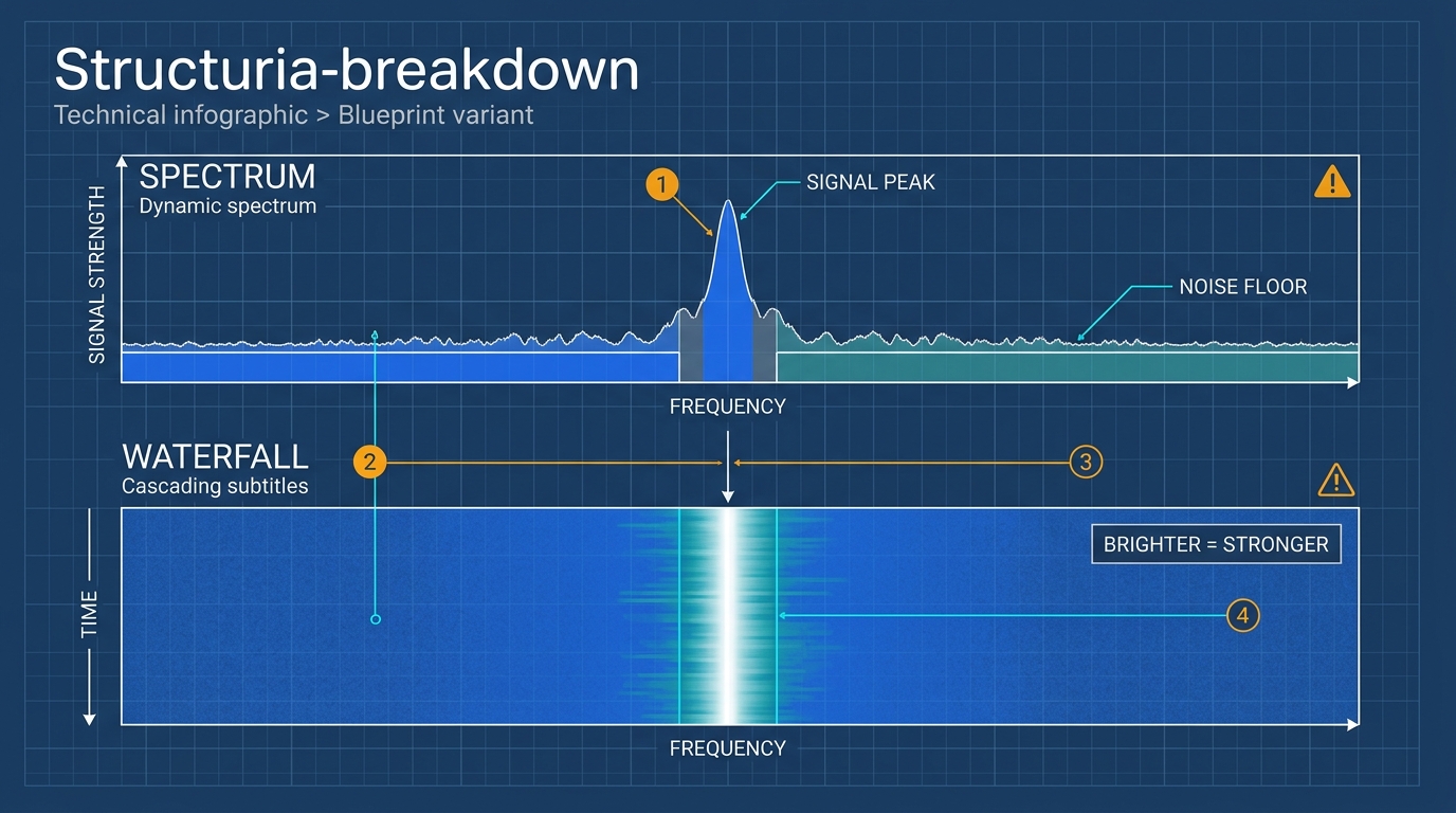
7.2 Gain Staging and Overload Prevention
08 Connecting to a Computer (Tethered SDR Mode)
Four System Operating Modes
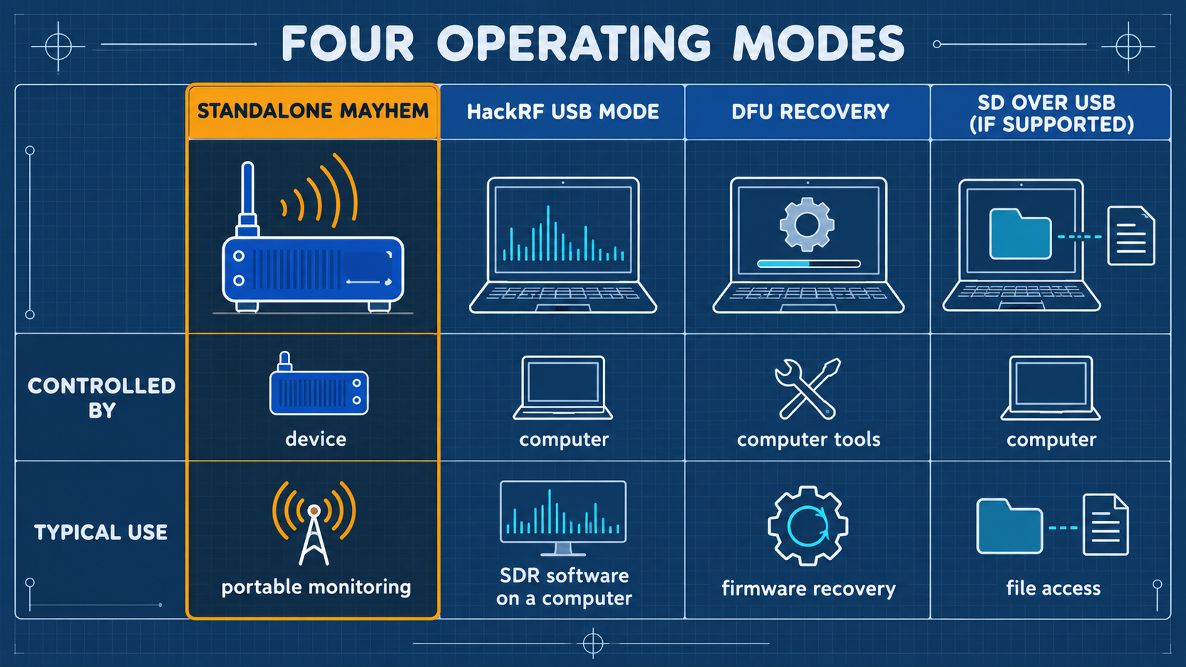
- Standalone PortaPack: Untethered portable field operation.
- HackRF USB Mode: Connects to GQRX, SDR++, GNU Radio via USB.
- SPI Flash Mode: Updating firmware via USB host.
- DFU Recovery Mode: Hardware unbricking via LPC43xx ROM bootloader.
09 Elective Advanced Reception: APRS, POCSAG, BLE, and ADS-B
- APRS Packet Decoding: Decode amateur 144.390 MHz position reports directly to offline maps.
- POCSAG Pager Monitoring: Decode alphanumeric laboratory paging signals.
- BLE Beacon Monitoring: Capture 2.4 GHz advertising channel packets.
- ADS-B Aircraft Telemetry (1090 MHz): Track commercial aviation altitude, callsigns, and GPS coordinates in real-time.
10 Laboratory Authorized Wired Capture, One-Shot Replay, and TX Experiments
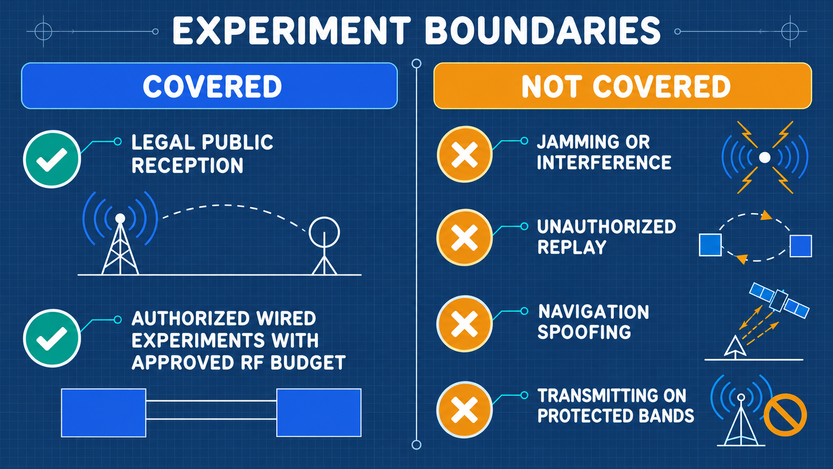
Open-air transmission is strictly illegal. All transmission must utilize a certified 50 dB attenuation chain.
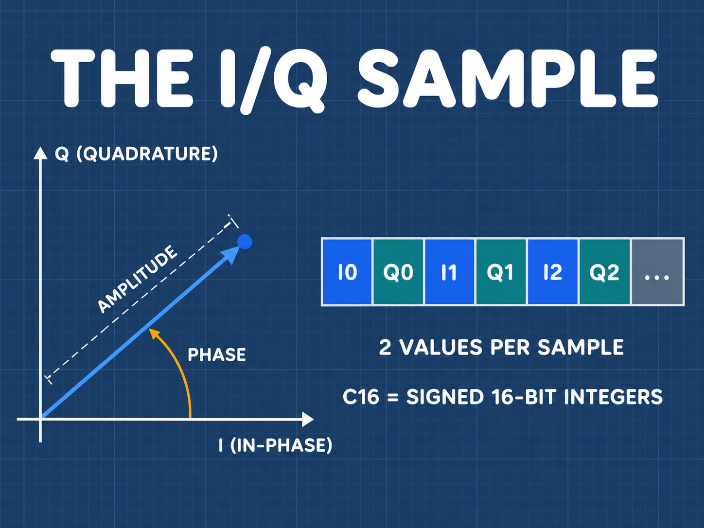
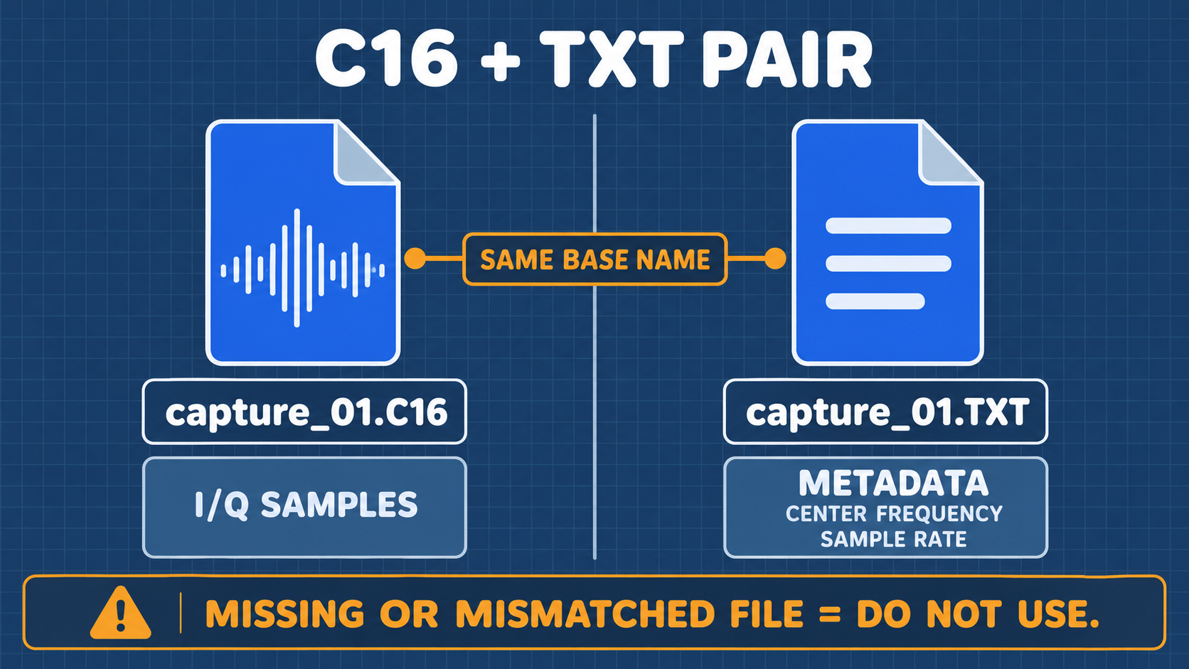
10.1 Quadrature I/Q Fundamentals and C16 Format
10.2 Power Budget Calculation and Safety Chain
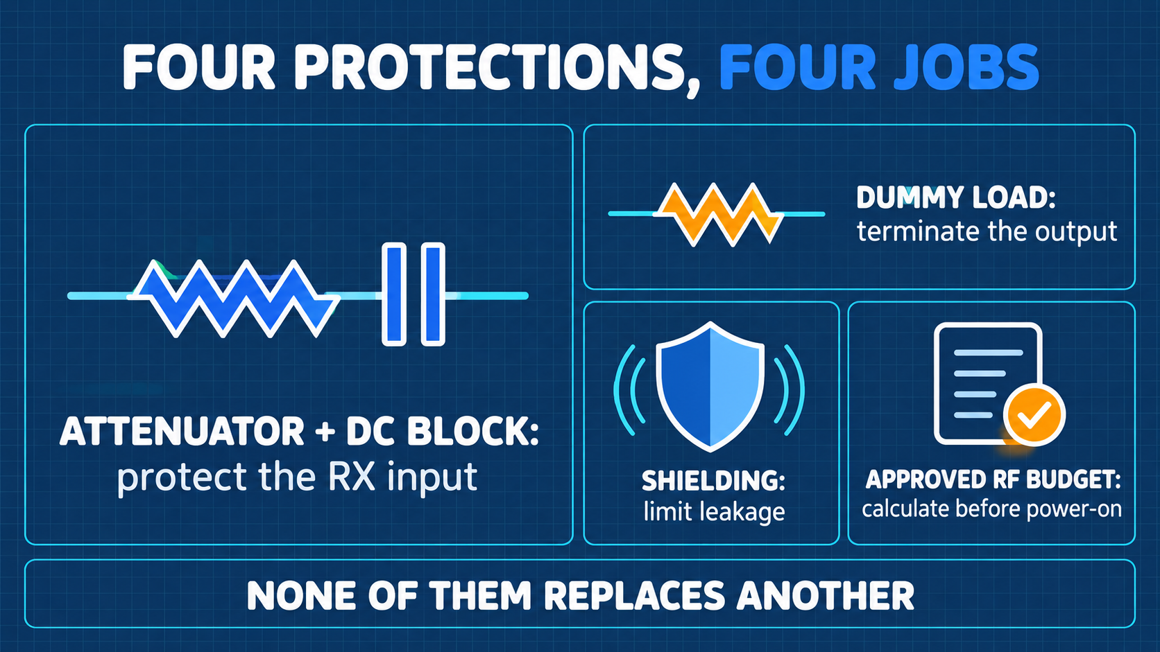
P_RX = P_TX (+10 dBm) - Attenuator (50 dB) - Cable Loss (1 dB) = -41 dBm
This maintains signal power far below the -10 dBm safe threshold and -5 dBm damage boundary.
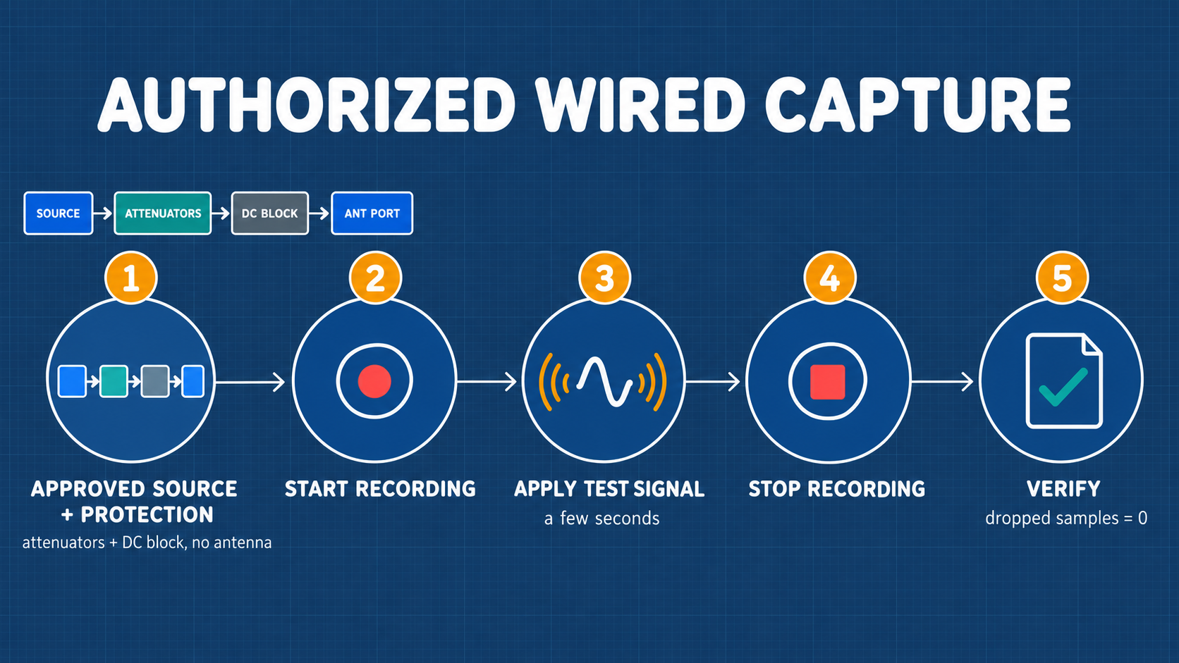
10.3 Wired Capture Workflow
10.4 Strict One-Shot Replay Workflow
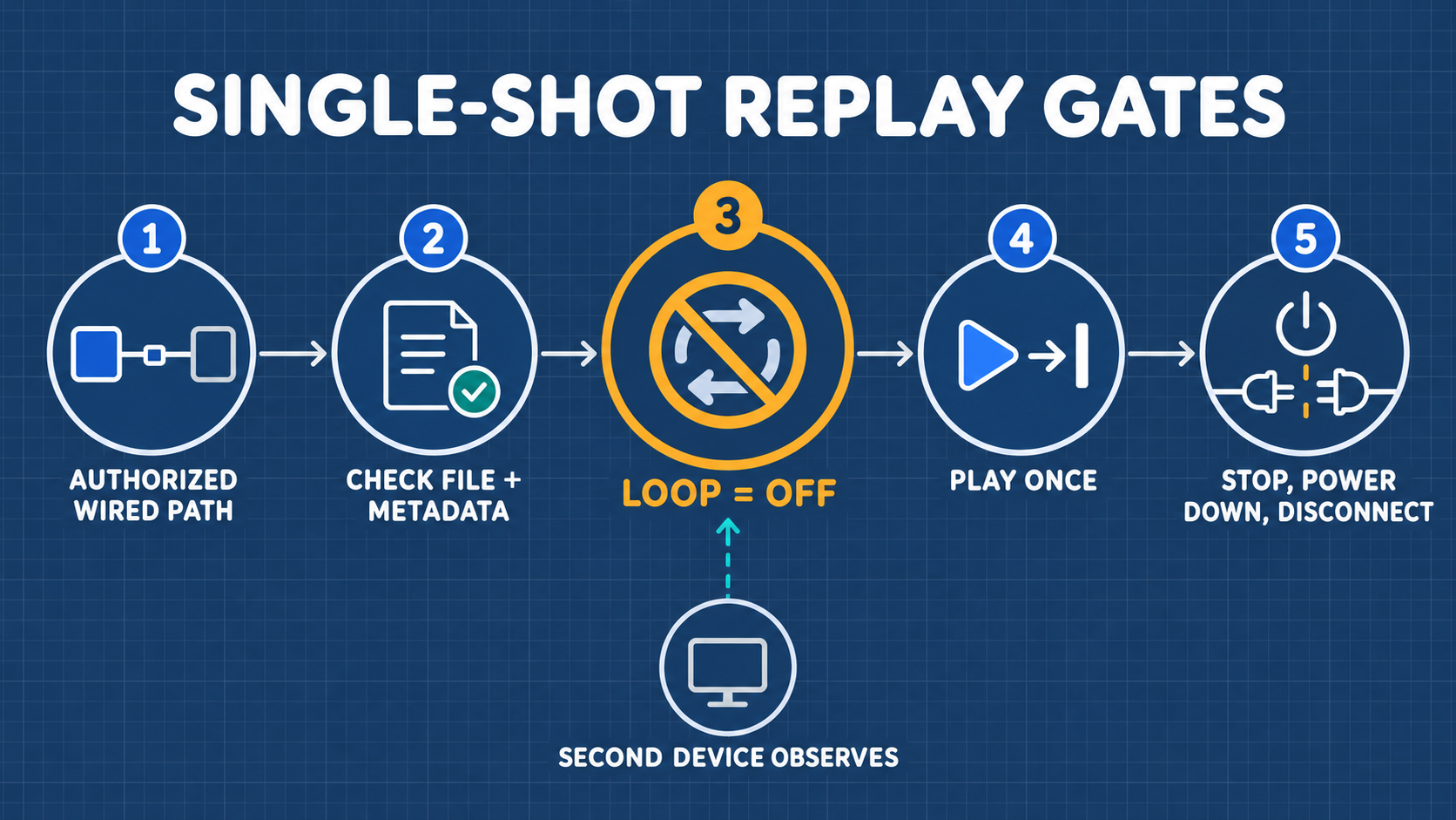
- Set
Looptoggle strictly to OFF. - Trigger Play once.
- Immediately disengage coaxial cabling upon completion.
11 Advanced Maintenance: Firmware Updates and DFU Recovery
11.1 Updating via Flash Utility
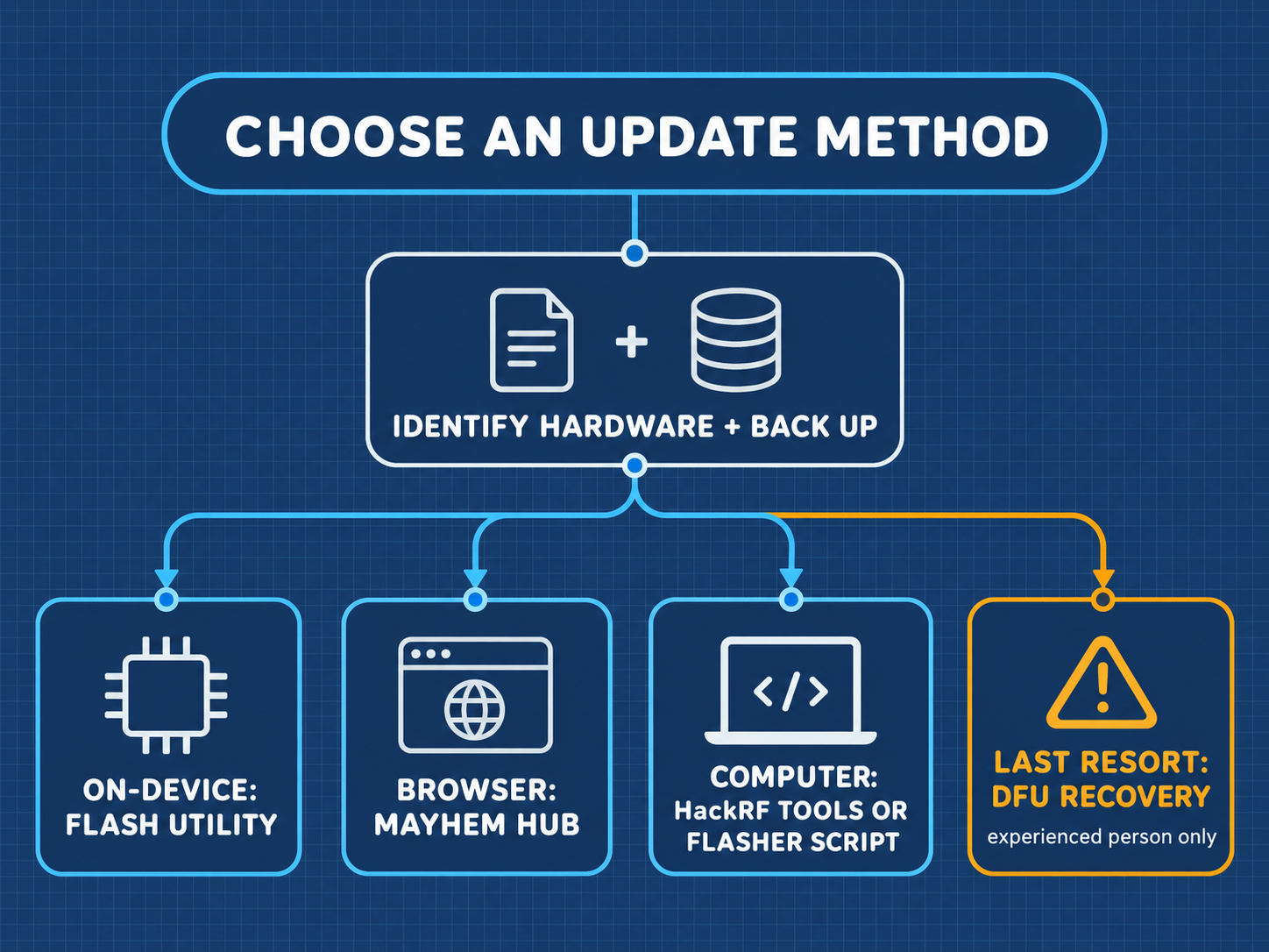
Download .ppfw.tar with target hpro, copy to microSD root, execute via Utilities → Flash Utility.
11.2 Pro DFU Low-Level Recovery
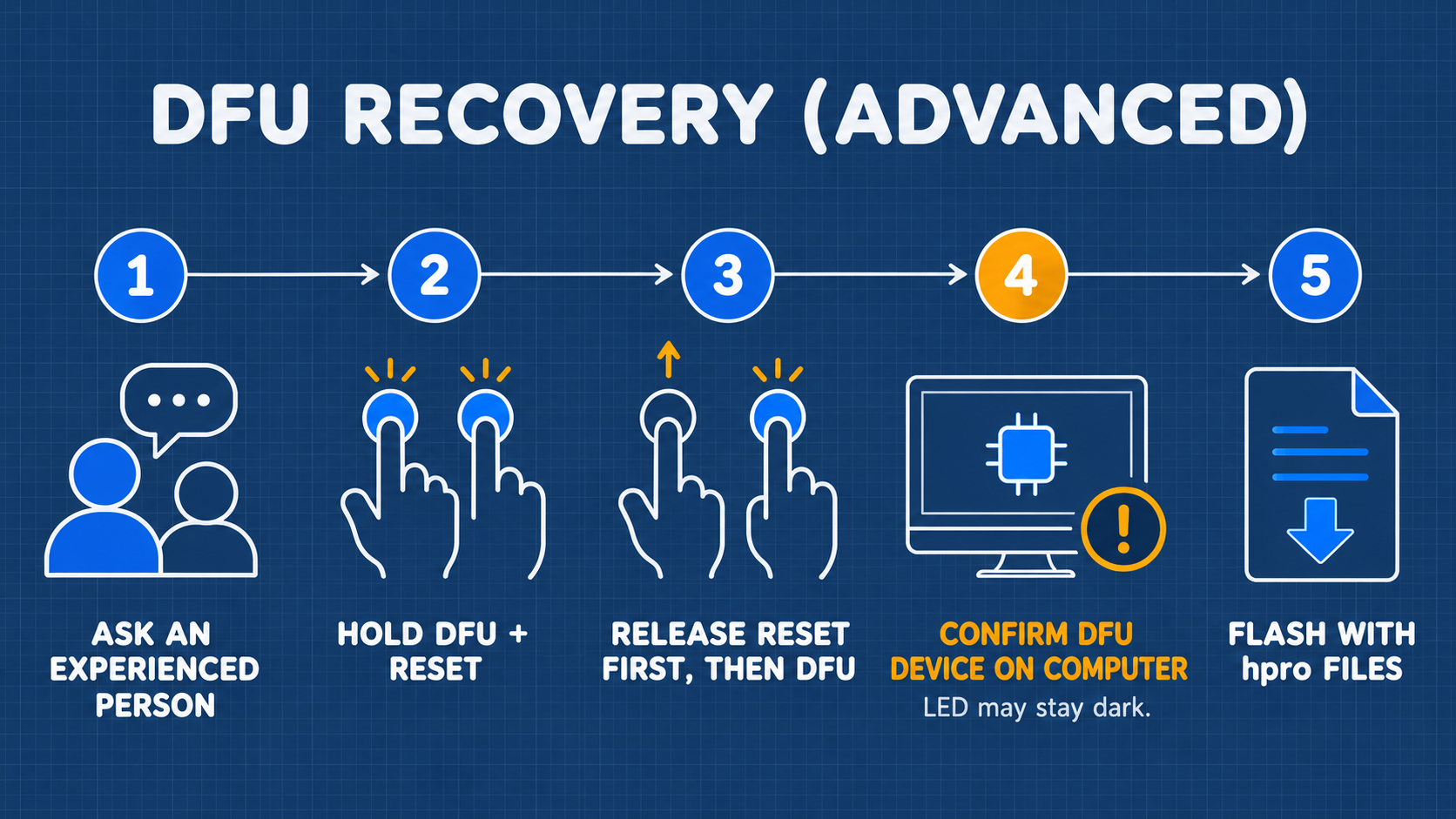
Hold the dedicated Pro DFU tactile switch while connecting USB-C, verify connection with dfu-util -l, and flash firmware_hpro.bin.
12 Troubleshooting and Frequently Asked Questions (FAQ)
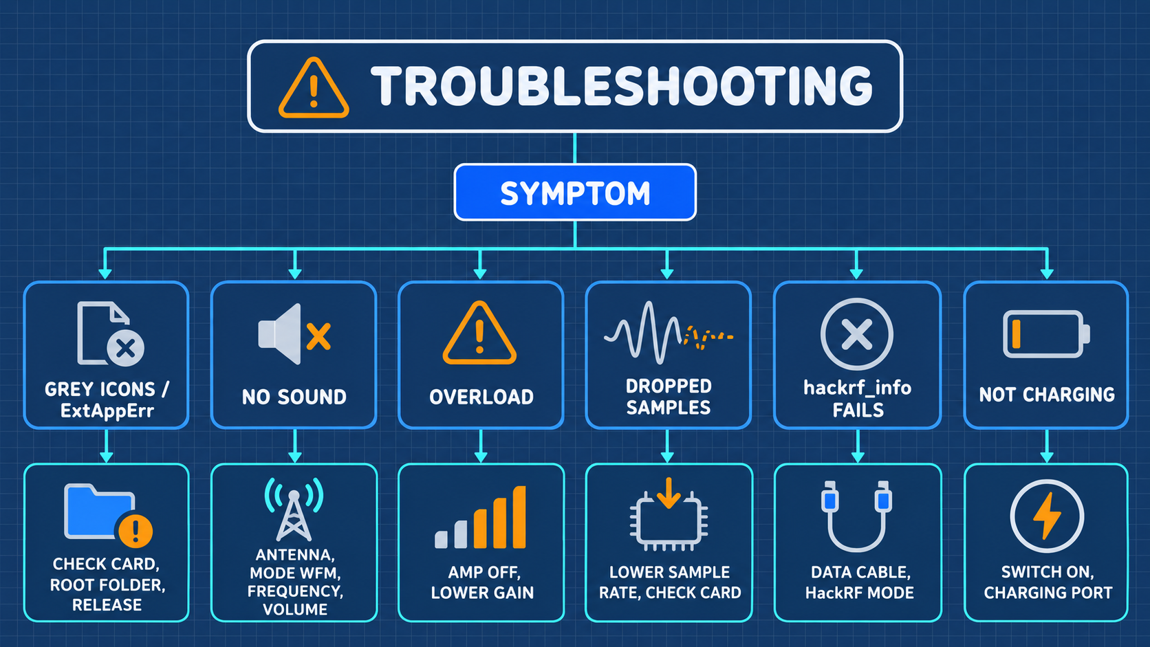
Troubleshooting Decision Matrix
Frequently Asked Questions (FAQ)
Q1: Why cannot the H4M Pro transmit and receive simultaneously?
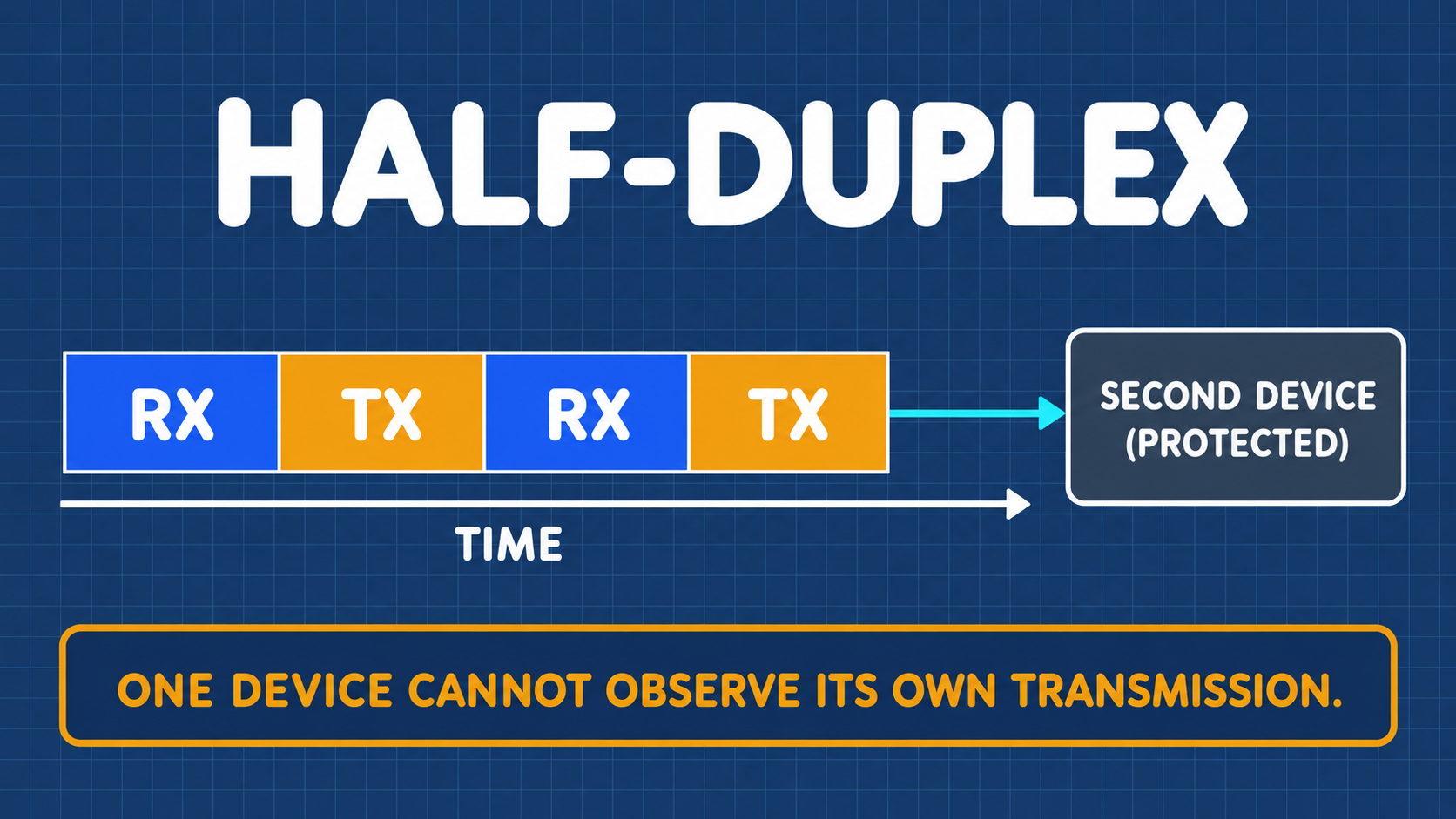
Answer: Even in the enhanced Pro R10C hardware, the core transceiver architecture remains half-duplex. Internal RF switches alternate between receive and transmit signal paths. Dual-device setups are required for simultaneous monitoring.
13 Core Technical Glossary and Concept Reference
- HackRF Pro R10C: Enhanced RF transceiver board revision featuring optimized high-frequency isolation and reduced clock spur leakage.
- 18650 Cell: Cylindrical lithium-ion rechargeable battery (18 mm diameter, 65 mm length) offering high discharge capacity.
hproTarget: Specific compile-time firmware build branch tailored to H4M Pro hardware drivers and power management ICs.
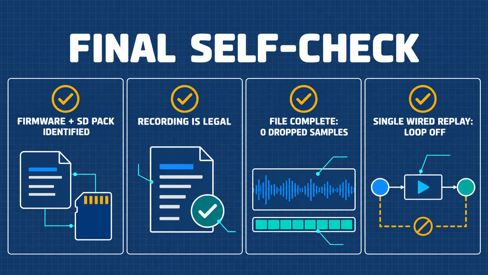
14 Learning Verification Checklist and Standard Lab Worksheet
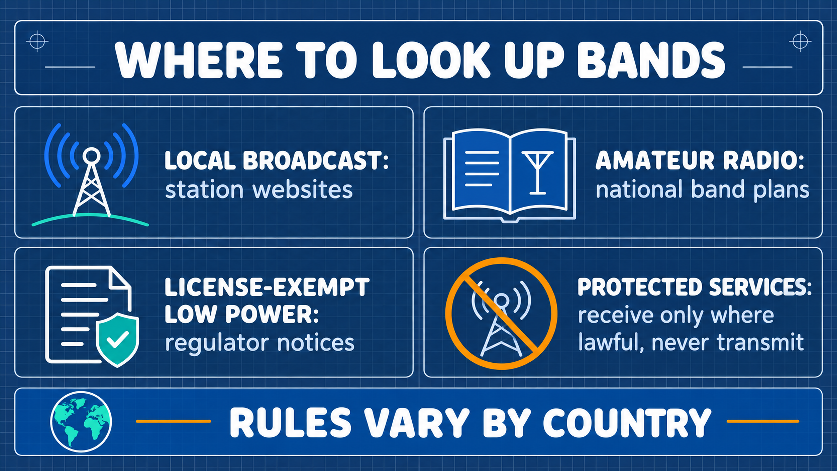
Appendix A: Frequency Band Allocation and Station Query Guide